
Aerial wind power generation device

A technology of wind power generation device and generator, which is applied in the direction of wind power generation, wind engine, wind motor combination, etc. It can solve the problems of mutual influence, small power generation, small generator, etc., and achieve stable balance, free from geographical restrictions, The effect of improving power generation efficiency

Active Publication Date: 2016-01-20
李明武
View PDF14 Cites 1 Cited by
  • Summary
  • Abstract
  • Description
  • Claims
  • Application Information

AI Technical Summary

Problems solved by technology

[0005] The Internet also disclosed AltaerosEnergies of the Massachusetts Institute of Technology (MIT), a high-altitude wind power generation device designed to float in the sky. "Donut" floats at an altitude of 300 to 600 meters. The accompanying picture shows that the helium balloon is huge in size, the generator is small, and the power generated by visual inspection is very small, and its commercial application value is not high
In addition, the biggest problem with this device is that the helium balloon’s balance motion and work motion are coupled and interact with each other, making it difficult to design an optimal control mode for balance and work, and it is difficult to guarantee continuity and stability, and the utilization rate of wind energy is not high

Method used


Image

  • Aerial wind power generation device
  • Aerial wind power generation device
  • Aerial wind power generation device

Examples


Embodiment

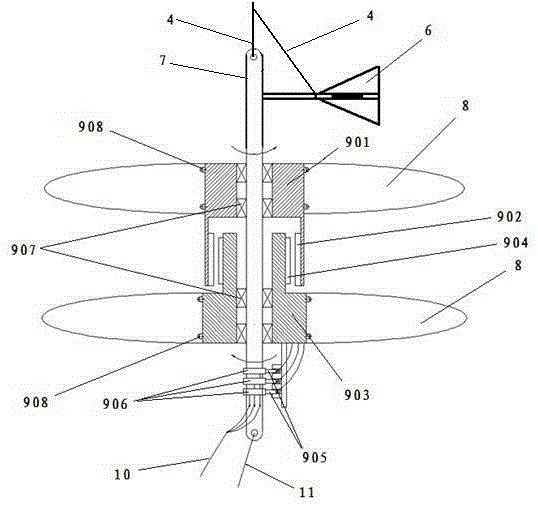
[0022] Example: such as figure 1 As shown, the concave floating body 1 is made into a boat shape or an umbrella shape. When the concave floating body 1 is made into a boat shape, a wind vane 3 is arranged at the tail, and the wind vane 3 consists of a horizontally arranged arc plate and an upper middle position It is composed of a curved plate arranged vertically, similar to the empennage of an airplane. The effect of the wind vane 3 can make the head of the boat-shaped concave floating body 1 face the direction of the wind under the blowing of the wind, so that the concave floating body 1 can obtain maximum lift and buoyancy. The production material of inner concave floating body 1 adopts modern airship production material, and is woven into by man-made materials such as terylene, polyester fiber, Mylar. Mylar material is a tough polyester polymer with good heat resistance, surface smoothness, transparency and mechanical flexibility. It is a famous brand of polyethyleneterep...


PUM


Abstract

The invention discloses an aerial wind power generation device. The aerial wind power generation device comprises an inwards-concave floating body, fixing rings, draw cords, a movable connector, a level wind direction rudder, a power generator set, inwards-concave wind wheels, bearings, bolts, a cable, a rein, winches, a transformer substation and a power grid. The aerial wind power generation device is mainly characterized in that the fixing rings are arranged at the edges of the inwards-concave floating body, and connected with one end of the movable connector through the corresponding draw cords; the other end of the movable connector is connected with one end or the two ends of a power generator shaft through the corresponding draw cords; the power generator shaft is connected with a stator and a rotor through the bearings; the inwards-concave wind wheels with opposite hook faces are arranged on the periphery of the stator and the periphery of the rotor; the end, provided with a collecting ring, of the power generator shaft is connected with the corresponding winch through the rein; and a wire led out from the collecting ring is connected with the transformer substation through the cable and is further connected to the power grid. The aerial wind power generation device is high in safety, good in balancing stability, high in wind energy use ratio, good in power generation effect, convenient to maintain and long in service life, and investment is saved.

Description

technical field [0001] The invention relates to a wind power generating device, in particular to an aerial wind power generating device. Background technique [0002] The wind has been used by people for a long time-mainly through windmills to pump water, grind flour, etc., but now, people are interested in how to use wind to generate electricity. Wind power is the conversion of wind kinetic energy into electrical energy. The principle of wind power generation is to use the wind to drive the blades of the windmill to rotate, and then increase the speed of rotation through the speed increaser to drive the generator to generate electricity. According to the current windmill technology, power generation can be started at a breeze speed (the degree of breeze) of about three meters per second. The wind wheel is an important component that converts the kinetic energy of the wind into mechanical energy. At present, it is mostly made of fiberglass or other composite materials (suc...

Claims


Application Information

Patent Timeline
Patent Type & Authority Applications(China)
IPC IPC(8): F03D9/30F03D80/00
CPCY02E10/72Y02E10/728
Inventor 李明武李智杰
Owner 李明武
Learn More