Embedded track system

An embedded track and track slab technology, which is applied in the field of rail transit, can solve the problems of low construction efficiency, large impact on the surrounding environment, and large maintenance workload, so as to facilitate construction and maintenance, improve dynamic performance, and reduce vibration and noise. Effect

Inactive Publication Date: 2016-01-20
CHENGDU XINZHU ROAD & BRIDGE MASCH CO LTD
View PDF6 Cites 4 Cited by
  • Summary
  • Abstract
  • Description
  • Claims
  • Application Information

AI Technical Summary

Problems solved by technology

[0003] 1. During the entire construction process, there are many procedures, low construction efficiency, long construction period, and great impact on the surrounding environment;
[0004] 2. After installation, the fasteners are easy to loosen during use. In order to ensure driving safety, the fasteners need to be checked and re-tightened frequently. The maintenance workload is heavy and the cost is high, which puts forward higher requirements for operation and management;
[0007] 1. The embedded load-bearing track is mainly supported by points, and its support effect is not good. The backing plate plays a supporting role under the rail, and the backing plate is laid intermittently and cannot be laid continuously;
[0008] 2. Fasteners or other anchors are required for fixing;
[0010] 4. The embedded load-bearing track has a small load-bearing area and can only be used for standard rails. It is inconvenient to use in grooved rails, and it does not solve the problem of slow construction of traditional rails

Method used


Image

  • Embedded track system
  • Embedded track system
  • Embedded track system

Examples


Embodiment 1

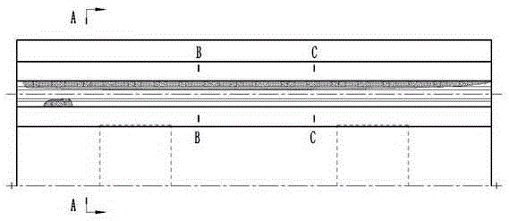
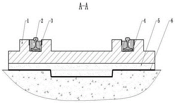
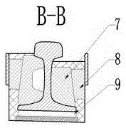
[0035] An embedded track system, comprising a foundation, a prefabricated track slab 1 and a steel rail 2, on the prefabricated track slab 1 corresponding to the width of the train wheel set, two rail bearing grooves with a slope at the bottom are provided in parallel; in the rail bearing groove, first Continuously lay the elastic backing plate 4, and then discretely set the height-adjusting backing plate 9 at the bottom that also has the same slope as the bottom of the rail bearing groove, and then set the rail 2 in the groove; 7 and the rail bearing groove wall are provided with a wedge-shaped block 8 to adjust the lateral position of the rail 2; the polymer castable 3 is poured into the rail bearing groove to fill up the remaining space; combined.

[0036] The elastic backing plate 4 is made of polyurethane foam backing plate with a length of 1 meter or 1.5 meters.

[0037] The height of the polymer castable 3 is different on both sides of the rail 2, wherein the height of...

Embodiment 2

[0041] like figure 1 , 2 , Shown in 3 and 4, a kind of embedded track system comprises foundation, prefabricated track slab 1 and steel rail 2, and the width of corresponding train wheel pair on described prefabricated track slab 1 is provided with the rail bearing groove that two bottoms have gradient in parallel; In the rail bearing groove, the elastic backing plate 4 is continuously laid first, and then the height-adjusting backing plate 9 with the same slope as the bottom of the rail bearing groove is discretely arranged, and then the steel rail 2 is set in the groove; block 7, and set a wedge-shaped block 8 between the prefabricated block 7 and the rail bearing groove wall to adjust the lateral position of the rail 2; pour polymer castables 3 into the rail bearing groove to fill up the remaining space; form an adjustment layer 5 by cast-in-place concrete Combine the prefabricated track slab 1 with the foundation.

[0042] The elastic backing plate 4 is made of polyureth...


PUM


Abstract

The invention discloses an embedded track system. The embedded track system comprises a base, a prefabricated track plate and steel rails, and two rail support grooves whose bottom portions have gradients are arranged in parallel corresponding to the width of a train wheel pair on the prefabricated track plate; in the rail support grooves, elastic cushion plates are firstly continuously laid, then height adjusting backing plates whose bottom portions also having the same gradients as the bottom portions of the rail support grooves are arranged in a discretely mode, and then the steel rails are arranged in the grooves; prefabricated sections are adhered to the two sides of each steel rail, and wedge blocks are arranged between the prefabricated sections and the walls of the rail support grooves for adjusting transverse positions of the steel rails; high-molecular castables are cast in the rail support grooves for filling residual space; and an adjustment layer is formed through cast-in-situ concrete for combining the prefabricated track plate with the base. The embedded track system has the following advantages: the construction cycle of a track line is shortened, and the construction quality is effectively guaranteed; vibration and noise are low; and the service life of the track line is longer.

Description

technical field [0001] The invention relates to the technical field of rail transportation, in particular to an embedded rail system. Background technique [0002] In traditional rail transit, rails are fixed with rail bearings or sleepers by fasteners, and then placed on ballasted or ballastless track beds. This approach has many disadvantages: [0003] 1. During the entire construction process, there are many procedures, low construction efficiency, long construction period, and great impact on the surrounding environment; [0004] 2. After installation, the fasteners are easy to loosen during use. In order to ensure driving safety, the fasteners need to be checked and re-tightened frequently. The maintenance workload is heavy and the cost is high, which puts forward higher requirements for operation and management; [0005] 3. For the large-volume traffic such as trains, problems such as rail wear and vibration and noise are gradually becoming prominent. [0006] There...

Claims


Application Information

Patent Timeline
Patent Type & Authority Applications(China)
IPC IPC(8): E01B1/00E01B2/00E01B19/00
Inventor 焦洪林罗炯杨刚刘光胜杨强
Owner CHENGDU XINZHU ROAD & BRIDGE MASCH CO LTD
Why Eureka
Try Eureka