A large-face milling fixture for disk parts

A disc-type parts and large-face technology, which is applied in the field of disc-type parts milling large-face fixtures, can solve the problems of fixed clamping and difficult milling processing of disc-type parts, and achieve the effect of firm clamping

Active Publication Date: 2018-02-16
WUHU HENGHAO MACHINERY MFG
View PDF5 Cites 0 Cited by
  • Summary
  • Abstract
  • Description
  • Claims
  • Application Information

AI Technical Summary

Problems solved by technology

But under normal circumstances, it is difficult to fix and clamp disc parts with the fixtures that come with conventional milling machines, and it is difficult to carry out subsequent milling.

Method used


Image

  • A large-face milling fixture for disk parts
  • A large-face milling fixture for disk parts
  • A large-face milling fixture for disk parts

Examples


Embodiment Construction

[0018] In order to make the technical means, creative features, goals and effects achieved by the present invention easy to understand, the present invention will be further elaborated below.

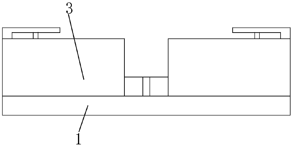
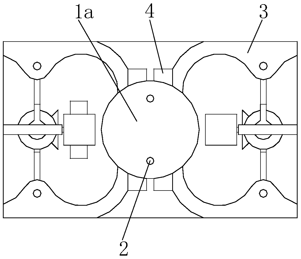
[0019] Such as Figure 1 to Figure 5 As shown, a fixture for milling large surfaces of disk parts mainly includes a base 1 and a placement groove 1a at the center of the base 1, and a positioning pin 2 is installed on the placement groove 1a. When in use, the disc parts can be placed in the placement groove 1a and positioned with the positioning pin 2 .

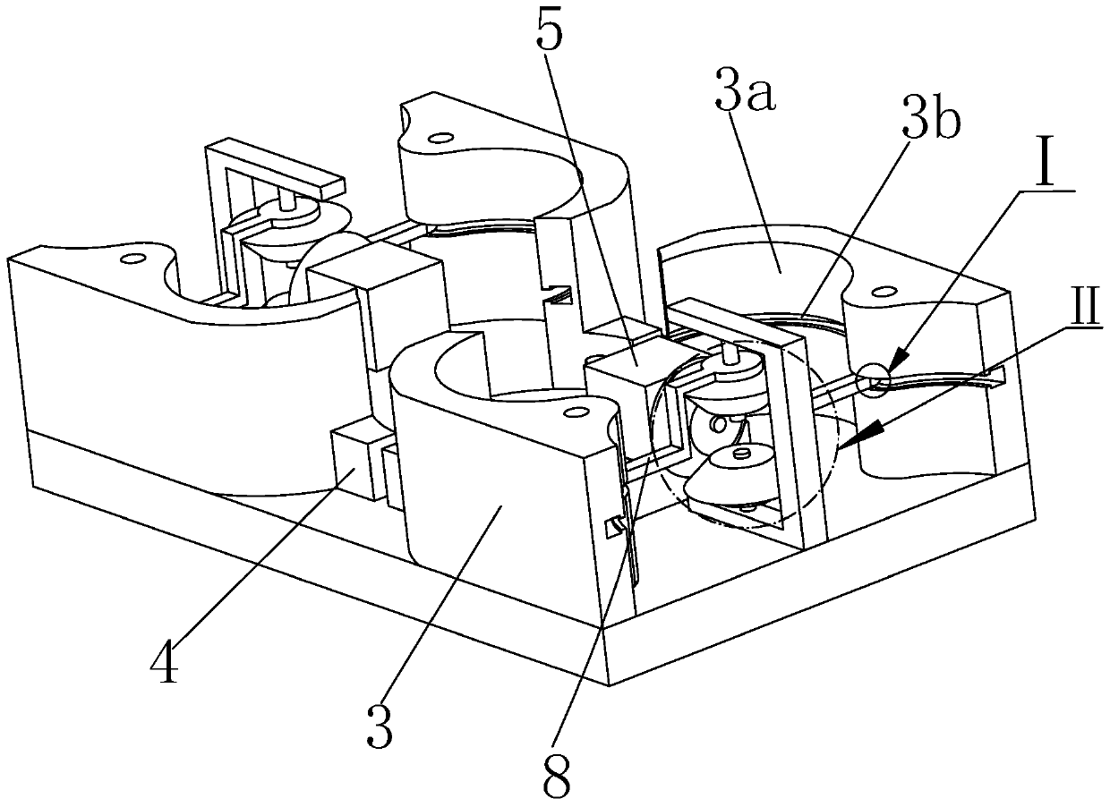
[0020] The four sides of the base 1 are hingedly mounted with driving plates 3 , and each of the driving plates 3 is provided with a clamping block 4 at one end close to the placement groove 1a.

[0021] The drive plates 3 are all provided with a raised arc surface 3a at one end close to the front and rear center of the base 1, and each arc surface 3a is provided with an arc slideway 3b matching its own arc extension direction.

[00...


PUM


Abstract

The invention relates to a large face milling clamp for disc type parts. The large face milling clamp mainly comprises a base and a containing groove. A locating pin is installed on the containing groove. Driving plates are hinged to and installed on the periphery of the base. Clamping blocks are arranged at the ends, close to the containing groove, of the driving plates. Protruding arc faces are arranged at the ends, close to the front-back center of the base, of the driving plates. Arc sliding channels matched with the arc extending directions of the arc faces are formed in the arc faces. Motors are installed on the left side and the right side of the base and are connected with main driving bevel gears. Joint bevel gears are meshed with the upper portions and the lower portions of the main driving bevel gears. The joint bevel gears are coaxially connected with joint connecting plates. Spherical bodies installed in the arc sliding channels in a sliding manner are arranged at the ends, away from the joint bevel gears, of the joint connecting plates. According to the large face milling clamp for the disc type parts, on the basis that the disc type parts are located, the four driving plates can be controlled at a time to clamp the disc type parts through transmission of an axle, clamping is firm, and the milling quality of the parts can be indirectly improved.

Description

technical field [0001] The invention relates to the field of mechanical processing fixtures, in particular to a large surface milling fixture for disk parts. Background technique [0002] Generally speaking, the surface of disk parts often requires high machining accuracy, so the surface of conventional disk parts must be milled after casting. However, under normal circumstances, it is difficult to fix and clamp the disk parts with the fixtures on the conventional milling machine, and then it is difficult to perform subsequent milling. Contents of the invention [0003] Aiming at the defects of the above-mentioned technologies, the present invention proposes a large surface milling fixture for disc parts that can be conveniently milled. [0004] A large surface milling fixture for disk parts mainly includes a base and a placement groove at the center of the base, and a positioning pin is installed on the placement groove. When in use, the disk parts can be placed in the ...

Claims


Application Information

Patent Timeline
Patent Type & Authority Patents(China)
IPC IPC(8): B23Q3/06
CPCB23Q3/062
Inventor 袁道华
Owner WUHU HENGHAO MACHINERY MFG
Why Eureka
Try Eureka