Milling machine for construction machinery
A technology for construction machinery and milling machines, which is applied in the field of construction machinery, can solve problems such as poor milling quality and unstable operation, and achieve the effect of improving adjustment efficiency and improving milling quality
- Summary
- Abstract
- Description
- Claims
- Application Information
AI Technical Summary
Problems solved by technology
Method used
Image

Examples
Embodiment 1
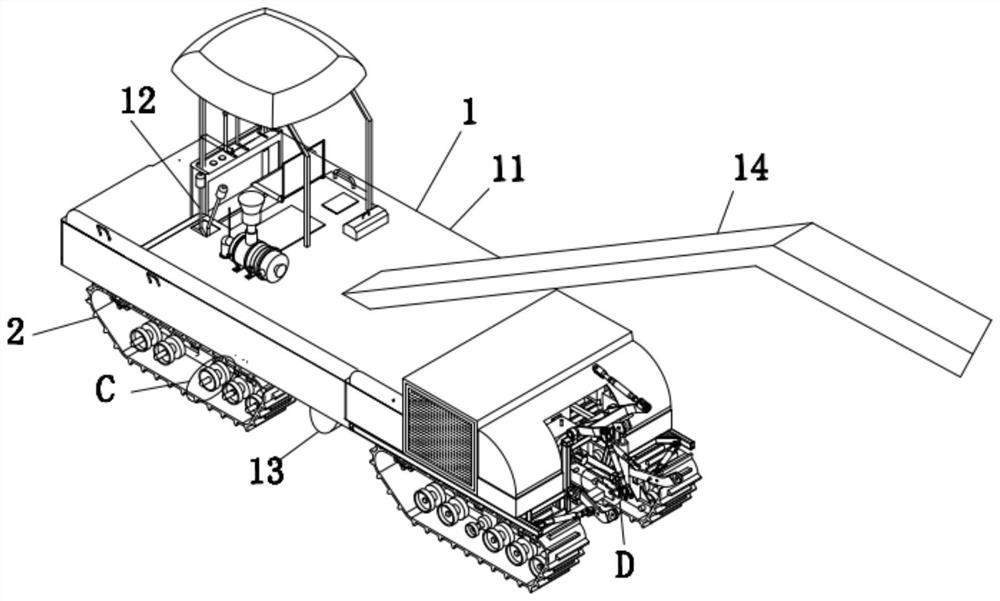
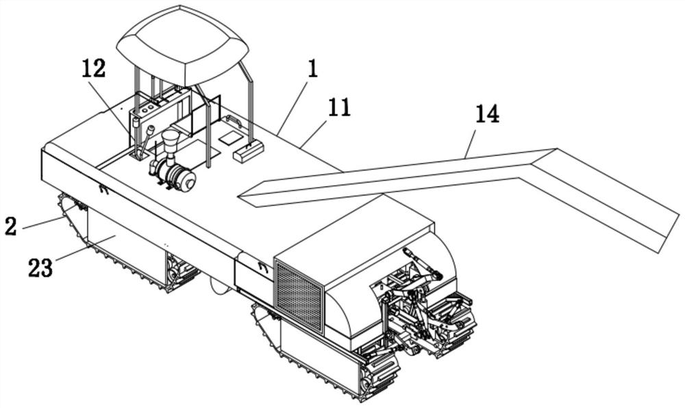
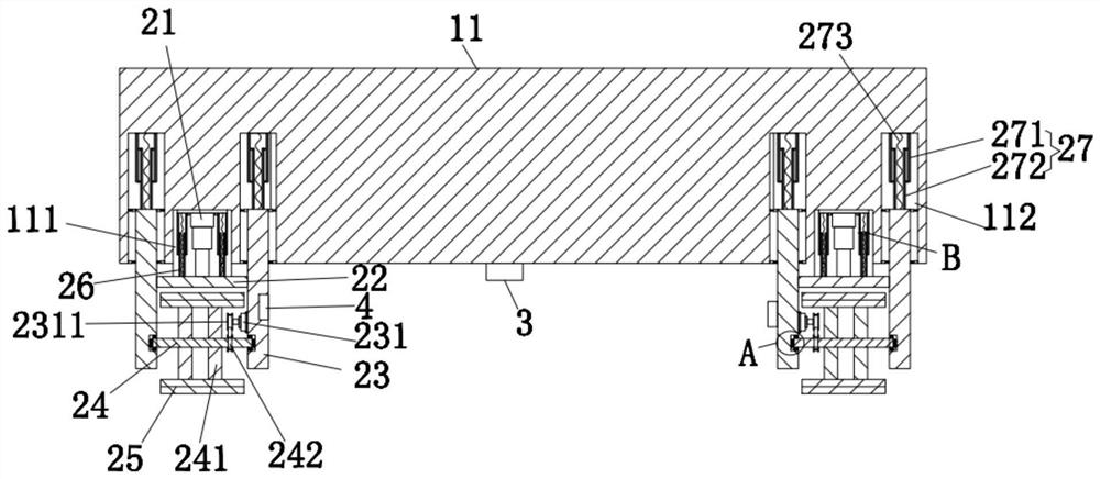
[0043] Such as figure 1 , figure 2 , image 3 with Image 6A milling machine for construction machinery, comprising a milling machine body 1, the milling machine body 1 includes a body 11, a control mechanism 12 is provided on the top left side of the body 11, a milling mechanism 13 is provided at the bottom middle of the body 11, and Comprising a waste material conveying mechanism 14 that cooperates with the milling mechanism 13, the four corners of the lower end surface of the body 11 are all provided with a drive mechanism 2, and the drive mechanism 2 includes a hydraulic cylinder 21, which is installed on the bottom of the body 11, and the hydraulic cylinder 21 The lower end of the piston rod is welded to the middle part of the upper end surface of the horizontal plate 22, and the left and right sides of the horizontal plate 22 are welded with vertical plates 23, and a round rod 24 is installed rotating between the bottoms of the left and right vertical plates 23, and t...
Embodiment 2
[0065] The difference from Example 1 is that the outer walls of the driving wheel 241 and the driven wheel 28 are sprayed with an anti-skid layer, and the anti-skid layer is prepared by the following method:
[0066] Take the following raw materials and weigh them in parts by weight: 8 parts of carbon fiber powder, 2 parts of anti-aging agent, 4 parts of anti-corrosion and anti-mold agent, 5 parts of potassium silicate solution, 14 parts of nano-silica powder, 6 parts of defoaming agent, superfine silica 10 parts of aluminum acid powder, 18 parts of titanium dioxide, 5 parts of thickener, 12 parts of binder, 60 parts of distilled water;
[0067] S1: Material preparation: first weigh the above raw materials;
[0068] S2: Powder mixing: first add distilled water into the mixer, then add carbon fiber powder, nano-silica powder, ultra-fine aluminum silicate powder and titanium dioxide into the mixer, turn on the mixer for stirring, the temperature inside the mixer Stir for 20 min...
Embodiment 3
[0075] The difference from Example 2 is the preparation of the anti-skid layer, and its specific preparation method is as follows:
[0076] Take the following raw materials and weigh them by weight: 12 parts of carbon fiber powder, 4 parts of anti-aging agent, 6 parts of anti-corrosion and anti-mold agent, 7 parts of potassium silicate solution, 18 parts of nano-silica powder, 8 parts of defoaming agent, superfine silicon 12 parts of aluminum acid powder, 22 parts of titanium dioxide, 8 parts of thickener, 16 parts of binder, 80 parts of distilled water;
[0077] S1: Material preparation: first weigh the above raw materials;
[0078] S2: Powder mixing: first add distilled water into the mixer, then add carbon fiber powder, nano-silica powder, ultra-fine aluminum silicate powder and titanium dioxide into the mixer, turn on the mixer for stirring, the temperature inside the mixer Stir for 30 minutes at 60°C with a rotation speed of 50r / min;
[0079] S3: Feed again: add potassi...
PUM
 Abstract
Description
Claims
Application Information
 - R&D
- Intellectual Property
- Life Sciences
- Materials
- Tech Scout
- Unparalleled Data Quality
- Higher Quality Content
- 60% Fewer Hallucinations
Browse by: Latest US Patents, China's latest patents, Technical Efficacy Thesaurus, Application Domain, Technology Topic, Popular Technical Reports.
© 2025 PatSnap. All rights reserved.Legal|Privacy policy|Modern Slavery Act Transparency Statement|Sitemap|About US| Contact US: help@patsnap.com