Eureka AIR delivers breakthrough ideas for toughest innovation challenges, trusted by R&D personnel around the world.

Hall engine starting power supply system and method

A technology of Hall engine and power supply system, applied in machine/engine, starter parts, mechanical equipment, etc., can solve the problems of easy sudden flameout, low ignition success rate, large oscillating current, etc., to improve work reliability and stability, improve the success rate of startup, and suppress the effect of startup shock

Active Publication Date: 2016-01-13
NO 771 INST OF NO 9 RES INST CHINA AEROSPACE SCI & TECH
View PDF5 Cites 4 Cited by
  • Summary
  • Abstract
  • Description
  • Claims
  • Application Information

AI Technical Summary

Problems solved by technology

[0005] 1 The success rate of ignition is not high, and the ignition is easy to turn off suddenly at the moment of ignition;
[0006] 2. The start-up oscillating current of the anode of the engine is relatively large, which affects the life of the Hall electric propulsion system;
[0007] 3 At the moment of successful ignition, the working state of the anode power supply suddenly jumps from no load to full load, which has a large impact on the anode power supply system and the power supply bus, affecting the life of the anode power supply and easily triggering the bus overcurrent protection

Method used


Image

  • Hall engine starting power supply system and method
  • Hall engine starting power supply system and method
  • Hall engine starting power supply system and method

Examples


Embodiment Construction

[0027] The present invention will be further described in detail below in conjunction with specific embodiments, which are explanations of the present invention rather than limitations.

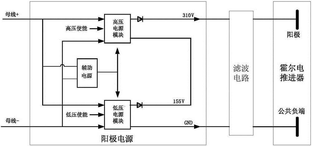
[0028] The present invention starts a power supply system for a Hall engine, such as figure 1 As shown, the anode power supply for the anode power supply includes a low-voltage power supply module and a high-voltage power supply module. The input terminals of the two modules are connected in parallel and the output terminals are connected in series. The output of the high-voltage power supply module is negative, and the output of the high-voltage power supply module is exactly the output positive of the anode power supply.

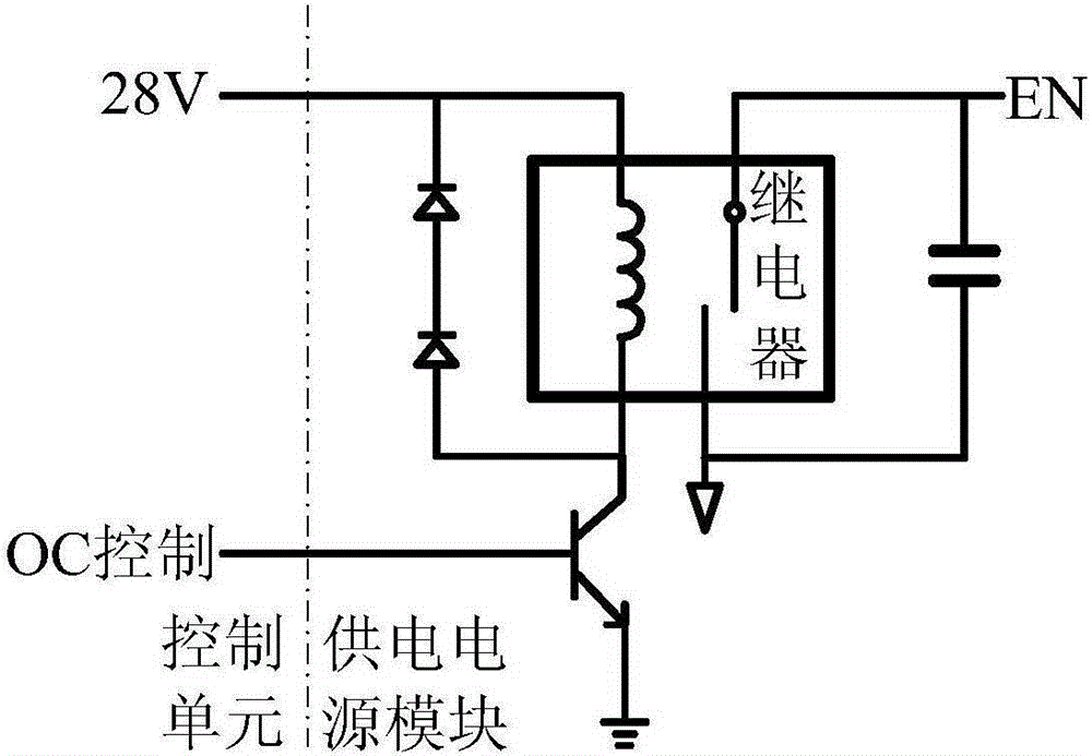
[0029] Both the high-voltage power supply module and the low-voltage power supply module are provided with enabling terminals, and an external control signal can act on the enabling terminals to control the operation and disconnection of the high and low-voltage power sup...


PUM


Abstract

The invention provides a hall engine starting power supply system and method, which are small in impact to a power supply system and a bus. The system comprises a positive power source and a filter circuit, wherein the positive power source comprises a low-voltage power source module, a high-voltage power source module, an auxiliary power source and an enable signal control circuit, wherein input ends of the low-voltage power source module and the high-voltage power source module are connected with each other in parallel; output ends are connected with each other in series; a negative output of the low-voltage power source module is taken as the negative output of a positive power supply source; a positive output of the high-voltage power source module is taken as the positive output of the positive power source; the positive output of the positive power source is connected with a positive input of the filter circuit; the negative output of the positive power supply source is connected with the positive input of the filter circuit; the positive output of the filter circuit is connected with an anode of a hall electric thruster; the negative output is connected with a cathode of the hall electric thruster; an input of the auxiliary power source is connected with a positive end and a negative end of the bus; an output of the auxiliary power source is connected with the low-voltage power source module and the high-voltage power source module respectively and provides electricity to the low-voltage power source module and the high-voltage power source module; and a control end of the auxiliary power source is connected with an output end of the enable signal control circuit.

Description

technical field [0001] The invention relates to a power supply scheme for the anode of a Hall electric thruster, in particular to a system and method for starting a Hall engine power supply. Background technique [0002] According to the working characteristics and power supply requirements of the anode of the Hall electric thruster, when the Hall electric thruster starts and works in a steady state, a 310V DC voltage is required to supply power to the anode of the Hall electric thruster. In a short period of time when the ignition was successful, the Hall electric thruster had a period of unstable operation, and then gradually stabilized. The duration of the unstable working state of the Hall electric thruster is related to the amplitude of the vibration and the method of power supply. [0003] The current method of supplying power to the anode of the Hall electric thruster is: when the ignition is started, add the 310V DC voltage output by the power supply to the anode of...

Claims


Application Information

Patent Timeline
Patent Type & Authority Applications(China)
IPC IPC(8): H02P1/10F03H1/00
Inventor 张建渝康小录成渭民王波张萍张新平
Owner NO 771 INST OF NO 9 RES INST CHINA AEROSPACE SCI & TECH
Why Eureka
Eureka Blog
Learn More