Self-cleaning injectors

A fuel injector and self-cleaning technology, which is applied in the direction of machines/engines, fuel injection devices, engine components, etc., to achieve the effect of increasing scouring force, improving carbon deposition, and reducing particles or colloids

Active Publication Date: 2017-10-31
CHANGZHOU INST OF MECHATRONIC TECH
View PDF5 Cites 0 Cited by
  • Summary
  • Abstract
  • Description
  • Claims
  • Application Information

AI Technical Summary

Problems solved by technology

[0002] At present, for a direct injection engine, due to the change in the structure of the fuel injection system, it is easier to form carbon deposits at the injector

Method used


Image

  • Self-cleaning injectors
  • Self-cleaning injectors
  • Self-cleaning injectors

Examples


Embodiment Construction

[0024] In order to make the content of the present invention more clearly understood, the present invention will be further described in detail below based on specific embodiments and in conjunction with the accompanying drawings.

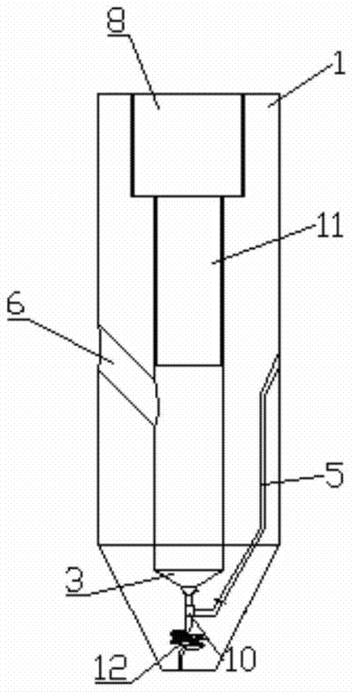
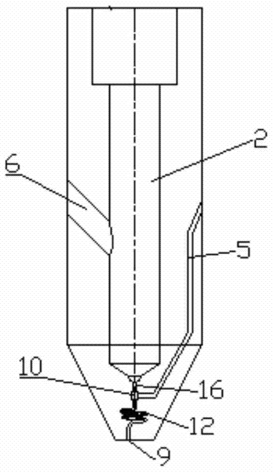
[0025] like Figure 1~6 Shown, a self-cleaning injector, it includes:

[0026] The main body, the main body has a housing 1, a plunger 11, a nozzle 9 and a controller 8, a cavity is arranged in the housing 1, and the plunger 11 is sealed and slipped in the cavity, and a cavity is opened on the housing 1 A liquid inlet hole 6 and a liquid return through hole 5, the controller 8 is connected to the plunger 11 in transmission, so that the controller 8 drives the plunger 11 to slide in the cavity, and the bottom end of the cavity is provided with a liquid outlet through hole 16, The liquid inlet hole 6 and the liquid return through hole 5 are respectively connected with the oil circuit of the fuel tank;

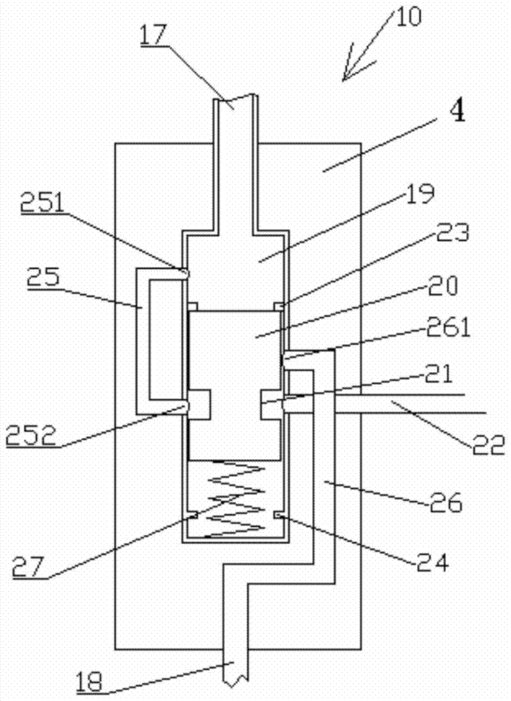
[0027] A reversing valve 10, the reversing va...


PUM


Abstract

The invention discloses a self-cleaning oil injector. The self-cleaning oil injector comprises a body and a reversing valve. The body is provided with a shell, a plunger, a nozzle and a controller. A cavity is formed in the shell. The plunger is in sealing sliding fit in the cavity. The shell is provided with a liquid inlet hole and a liquid returning through hole. The controller is in transmission connection with the plunger. A liquid outlet through hole is formed in the bottom end of the cavity. The oil inlet hole and the oil returning through hole are communicated with an oil path of an oil tank. The reversing valve is provided with a nozzle connecting pipe, the nozzle connecting pipe is communicated with the nozzle through a spiral bent channel, and the reversing valve is provided with an oil injecting state position and a non-oil-injecting sate position. According to the self-cleaning oil injector, the accumulated carbon on the inner wall of a fuel channel in the oil injector can be reduced, carbon particles or colloidal materials on the inner wall of a fuel channel at the lower end of the oil injector are cleaned, the particles or colloidal materials generated after combustion in an air cylinder are more hardly to reach the surface of a valve element, the carbon is prevented from being accumulated at the valve element, and accordingly the service life of the oil injector is prolonged.

Description

technical field [0001] The invention relates to a self-cleaning fuel injector. Background technique [0002] Currently, for a direct-injection engine, due to changes in the structure of the fuel injection system, carbon deposits are more likely to form at the injector. There are two main conditions for the formation of carbon deposits in the injectors of this type of engine. One is that the colloids produced by the self-oxidation of the fuel in a high-temperature environment decompose and deposit in the injectors to form carbon deposits; The carbon particles or colloids formed by the burning fuel deposit on the valve body of the fuel injector to form carbon deposits. Theoretically speaking, reducing the carbon deposit at the injector can cool the injector on the one hand, reduce the temperature of the fuel flowing through the passage, reduce the residence time in the passage, and reduce the colloid produced by self-oxidation; On the one hand, try to separate the fuel injec...

Claims


Application Information

Patent Timeline
Patent Type & Authority Patents(China)
IPC IPC(8): F02M61/16F02B77/04
Inventor 任萍丽鲁明张炎李彦
Owner CHANGZHOU INST OF MECHATRONIC TECH
Why Eureka
Try Eureka