Method for manufacturing tire molding die and tire molding die
A manufacturing method and tire forming technology, which are applied in the manufacture of tire forming molds and the fields of tire forming molds
- Summary
- Abstract
- Description
- Claims
- Application Information
AI Technical Summary
Problems solved by technology
Method used
Image
Examples
no. 1 approach
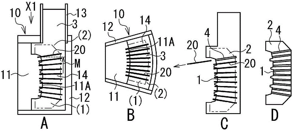
[0029] figure 1 is a sectional view showing the manufacturing process of the mold 1 of the first embodiment, in which figure 1 (A) shows the casting mold 10 when viewed from the side. figure 1 (B) is when from figure 1 The cross-sectional view of the casting mold 10 when viewed in the X1 direction of (A), figure 1 of (C) and figure 1 (D) are both the same as figure 1 (A) corresponds to the cross-sectional view of mold 1 (cast metal 2). exist figure 1 of (A), figure 1 of (B) and figure 1 In (C) of , the part (product part) which becomes the product of the mold 1 is shown by a two-dot chain line. figure 1 The arrow M shown in (A) of , indicates the moving direction of the surface of the molten metal 3 (schematically shown by the broken line) in the casting mold 10 .
[0030] As shown, the casting mold 10 includes: a main mold 11 for molding the cast metal 2 of the mold 1; a molding flask 12 for housing the main mold 11; and a stoke 13 for storing molten metal Metal 3. ...
no. 2 approach
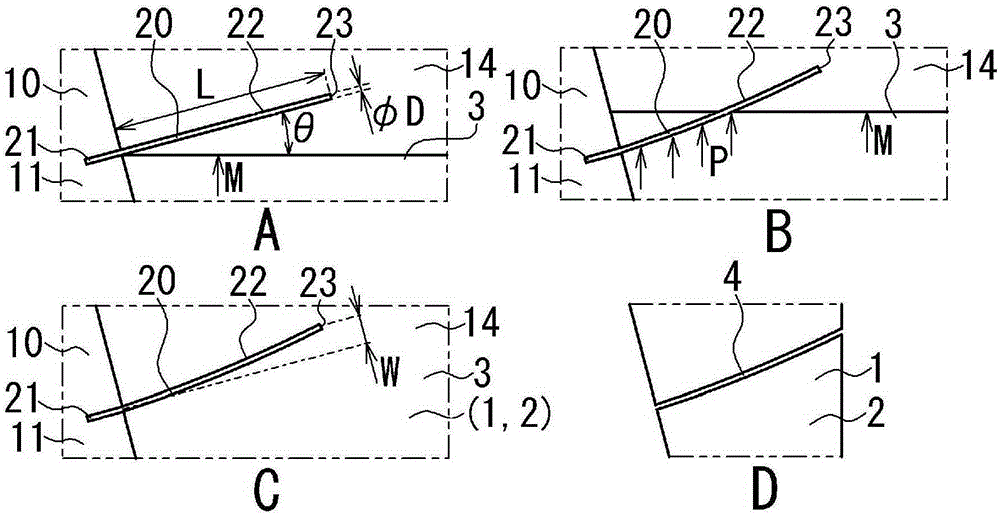
[0055] The aforementioned relational expressions (Formulas A to C) include the term sin(90-θ). Therefore, if the contact angle θ of the wire rod 20 is 90°, the bending amount W of the wire rod 20 is zero regardless of the conditions of the length L and the diameter D of the wire rod 20 . Focusing on this characteristic, in the second embodiment, the contact angle θ of the wire rod 20 is set to 90°, and the wire rod 20 is arranged in the casting space 14 .
[0056] Image 6 It is a diagram showing how the wire rod 20 is arranged in the second embodiment and showing the cross section of the casting mold 10 . in addition, Image 6 (B) is when from Image 6 A cross-sectional view of the casting mold 10 when viewed in the X2 direction in (A). exist Image 6 In the figure, the part (product part) which becomes the product of the mold 1 is shown by a two-dot chain line. Image 6 The arrows M shown represent the direction of movement of the surface of the molten metal 3 (schemat...
no. 3 approach
[0061] In the third embodiment, in addition to the foregoing embodiments, the thickness of the mold release agent 22 required to pull the wire rod 20 from the cast metal 2 is predicted, and the conditions for setting the thickness of the mold release agent 22 are also predicted. As a result, the wire rod 20 is reliably pulled out from the cast metal 2 while the bending deformation of the wire rod 20 is suppressed.
[0062] Figure 7 It is a figure for demonstrating the pulling-out of the wire rod 20. FIG.
[0063] As illustrated, after the molten metal 3 shrinks by solidification in the casting mold 10, the cast metal 2 shrinks by cooling (see Figure 7 of (A) to Figure 7 (C)). With this contraction, the pressure R (see Figure 7 (C)) is applied to the wire 20, so that the frictional force between the wire 20 and the cast metal 2 becomes larger. When the wire 20 is to be drawn from the cast metal 2 (see Figure 7 (D)), the pull-out resistance J is applied to the wire 20...
PUM
| Property | Measurement | Unit |
|---|---|---|
| particle diameter | aaaaa | aaaaa |
| water contact angle | aaaaa | aaaaa |
| length | aaaaa | aaaaa |
Abstract
Description
Claims
Application Information
 - Generate Ideas
- Intellectual Property
- Life Sciences
- Materials
- Tech Scout
- Unparalleled Data Quality
- Higher Quality Content
- 60% Fewer Hallucinations
Browse by: Latest US Patents, China's latest patents, Technical Efficacy Thesaurus, Application Domain, Technology Topic, Popular Technical Reports.
© 2025 PatSnap. All rights reserved.Legal|Privacy policy|Modern Slavery Act Transparency Statement|Sitemap|About US| Contact US: help@patsnap.com


