
A resistive variable memory and a method for increasing its positive and negative current difference

A resistive variable memory and resistive variable technology, applied in the field of resistive variable memory and improving its positive and negative current difference, can solve problems such as misreading of stored information, achieve broad application prospects, strong practicability, and improve reliability

Active Publication Date: 2018-10-30
FUZHOU UNIV
View PDF5 Cites 0 Cited by
  • Summary
  • Abstract
  • Description
  • Claims
  • Application Information

AI Technical Summary

Problems solved by technology

However, crosstalk currents in this architecture can lead to misreading of stored information

Method used


Image

  • A resistive variable memory and a method for increasing its positive and negative current difference
  • A resistive variable memory and a method for increasing its positive and negative current difference
  • A resistive variable memory and a method for increasing its positive and negative current difference

Examples


Embodiment 1

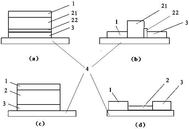
[0058] A resistive variable memory, its structure is as follows figure 1 As shown in (a), a glass substrate 4, ITO with a thickness of 200 nm is used as the first terminal electrode 3, ZnO with a thickness of 15 nm is used as the second resistive layer 22, and HfO with a thickness of 30 nm x The first resistive switch layer 21 and Ti with a thickness of 200 nm are used as the second terminal electrode 1 .

[0059] In order to increase the positive and negative current difference of the resistive variable memory, the specific manufacturing steps are as follows:

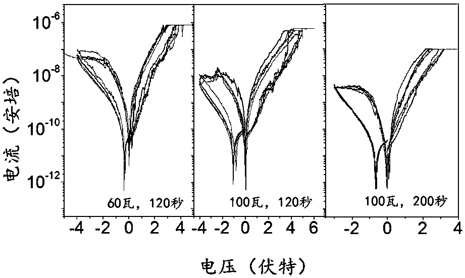
[0060] Put the glass substrate with the ITO conductive film into the vacuum chamber, and prepare 15nm ZnO as the second resistive layer 22 by magnetron sputtering; and (100 watts, 200 seconds) Ar plasma treatment of the second resistive layer 22 of ZnO with three pairs of parameters; followed by magnetron sputtering to prepare 30nm HfO x As the first resistive switch layer 21, thereby forming a double-layer storage m...

Embodiment 2

[0063] A resistive variable memory, its structure is as follows figure 1 As shown in (d), a PET substrate 4, Ti with a thickness of 200 nm is used as the first terminal electrode 3, a ZnO nanowire with a length of 10 μm and a diameter of 50 nm is used as the resistive dielectric layer 2, and the thickness is 200 nm. Ti is formed as the second terminal electrode 1 .

[0064] In order to increase the positive and negative current difference of the resistive variable memory, the specific manufacturing steps are as follows:

[0065] Sprinkle the ZnO nanowires on the PET substrate, and then make the first end electrode on the ZnO nanowires by magnetron sputtering, then use 100 watts Ar plasma to treat the ZnO nanowires for 120 seconds, and then place the ZnO nanowires on the ZnO nanowires. On the other end, the second end electrode is prepared by magnetron sputtering.

[0066] It can be seen from the test, such as Figure 4 As shown, the difference between the positive and negat...


PUM

PropertyMeasurementUnit
thicknessaaaaaaaaaa
areaaaaaaaaaaa
lengthaaaaaaaaaa

Abstract

The invention relates to a resistive random access memory and a method for improving a positive and negative current difference of the resistive random access memory. The resistive random access memory comprises a substrate, a first terminal electrode, a variable resistance medium layer and a second terminal electrode, wherein the first terminal electrode is arranged on the substrate and forms a good electric contact together with the substrate; the variable resistance medium layer is arranged at the left side or the upper part of the first terminal electrode; if the variable resistance medium layer is arranged at the left side of the first terminal electrode, the second terminal electrode is arranged at the left side of the variable resistance medium layer; if the variable resistance medium layer is arranged at the upper part of the first terminal electrode, the second terminal electrode is arranged at the upper part of the variable resistance medium layer; the variable resistance medium layer is a dual-layer variable resistance medium; and the dual-layer variable resistance medium is in a laminated structure formed by a first variable resistance layer and a second variable resistance layer. By plasma modification, defects are introduced into the medium or the medium surface, so that a negative current value is effectively suppressed; and the positive and negative current difference is greatly improved.

Description

technical field [0001] The invention belongs to the technical field of semiconductor memory, in particular to a resistive variable memory and a method for increasing its positive and negative current difference. Background technique [0002] Resistive RAM (RRAM) is usually composed of a simple sandwich structure (electrode / storage medium / electrode). By applying an electrical signal, the resistance state of the storage material is changed to achieve a bistable storage function. With the development of technology, memory tends to adopt criss-cross three-dimensional integration in order to obtain higher storage density. However, crosstalk currents in this architecture can lead to misreading of stored information. Therefore, improving the positive and negative current difference (or rectification characteristics) of the RRAM and obtaining the nonlinearity of the current-voltage characteristics can better suppress the crosstalk current flowing through the low-resistance memory c...

Claims


Application Information

Patent Timeline
Patent Type & Authority Patents(China)
IPC IPC(8): H01L45/00H01L27/24G11C13/00C23C14/35C23C16/44C23C14/22
Inventor 赖云锋曾泽村邱文彪程树英林培杰俞金玲周海芳郑巧
Owner FUZHOU UNIV
Learn More