


Quick Research
Generate reliable direction feasibility study reports for your R&D in just a few steps.

Technical Q&A
Discover and master advanced knowledge NOW. Basics, ideas, possibilities, all at once.

Find Solutions
As an expert in R&D theories, this can generate solutions to your technical problems instantly.

Evaluate Feasibility
Analyze your overall solution with one click, know your potential R&D risks in advance.

Monitor Landscape
Get weekly tech updates, stay abreast of the latest tech innovations and key insights.
Clamping wheel type manual transmission
A manual transmission, transmission technology, applied in the direction of vehicle gearbox, gear transmission, transmission components, etc., can solve the problems of insufficient torque, high manufacturing process requirements, high maintenance cost, and achieve stable changes in vehicle speed, high transmission efficiency, Easy-to-control effects
- Summary
- Abstract
- Description
- Claims
- Application Information
AI Technical Summary
Problems solved by technology
Method used
Image

Examples
Embodiment 1
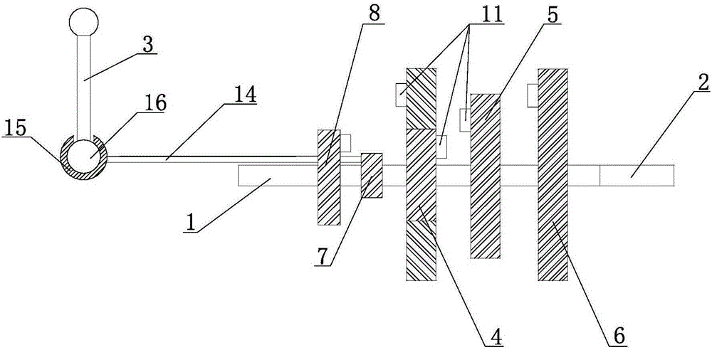
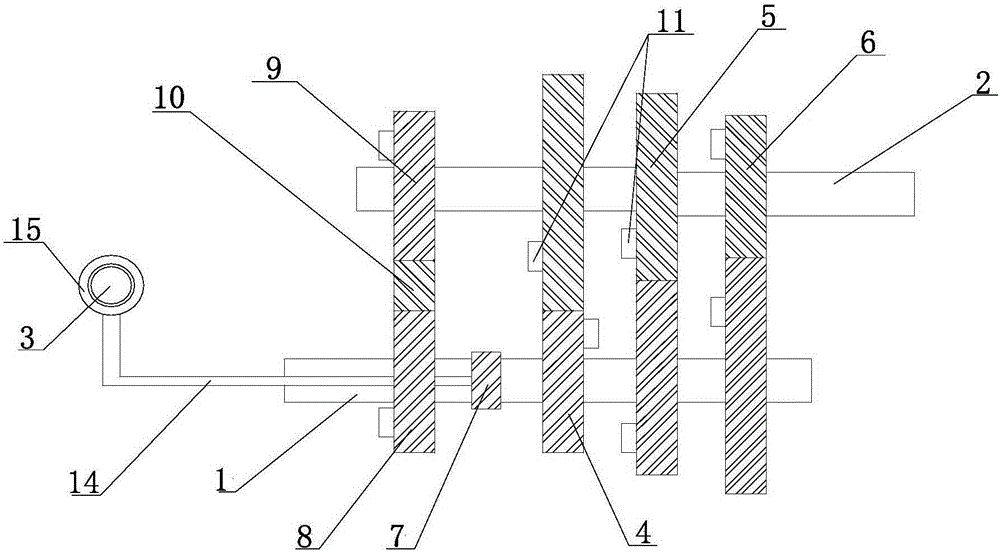
[0047] Such as figure 1 , 2 As shown, the present invention provides a novel manual transmission, which includes a transmission housing, an input shaft 1, an output shaft 2, a shift lever 3, a first gear control gear row 4, a second gear control gear row 5, and a third gear control gear Row 6, card wheel device 7 and flat pushing mechanism. The input shaft 1, the output shaft 2, the first-speed control gear row 4, the second-speed control gear row 5, the third-speed control gear row 6, the card wheel device 7 and the parallel push mechanism are all arranged in the transmission casing (not shown in the drawings) Inside, the shift lever 3 is located outside the transmission casing, and one end thereof extends into the transmission casing.
[0048] The first gear control gear row 4, the second gear control gear row 5, and the third gear control gear row 6 are all composed of a driving annular bevel gear and a driven annular bevel gear meshing with each other, and the first gear...
Embodiment 2
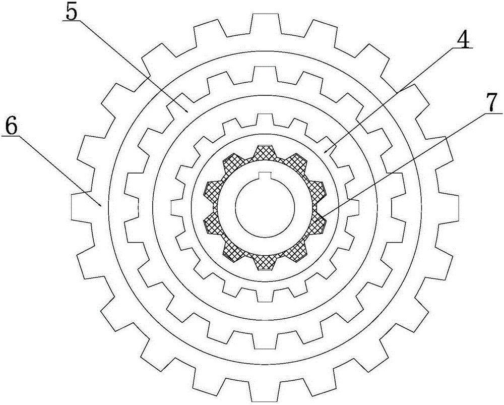
[0065] Such as Figure 6 As shown, the difference from Embodiment 1 is that this embodiment connects the input shaft 1 with all the driving ring bevel gears, and connects the output shaft 2 through all the driven ring bevel gears without contact, and relies on the card wheel device to realize The output shaft 2 is connected with the driven annular bevel gear on a certain gear control gear row. Other designs of this embodiment are all the same as Embodiment 1, and the working principle of this embodiment is:
[0066] When the card wheel device is a connecting gear
[0067] Taking a car as an example, initially, the shift lever 3 is located in the neutral position between the first gear and the parking gear. When starting the car, under the action of the engine, the input shaft 1 rotates, and drives all the driving ring bevel gears to rotate and the driven ring bevel gears to rotate together, while the output shaft 2 has no contact with the driven ring bevel gears at this time...
Embodiment 3
[0074] Such as Figure 7 As shown, the difference from the above-mentioned embodiments 1 and 2 is that in this embodiment, the input shaft 1 runs through all the driving ring bevel gears without contact, and at the same time, the output shaft 2 runs through all the driven ring bevel gears without contact, and set Two card wheel devices are provided, one card wheel device is used to realize the connection between the input shaft 1 and the active annular bevel gear on a certain gear control gear row, and the other card wheel device is used to realize the connection between the output shaft 2 and a certain gear position. Driven ring bevel gear connection on control gear row. The working principle of this embodiment is a combination of the working principles of the above-mentioned embodiments 1 and 2. Those skilled in the art can deduce the working principle of this embodiment without any doubt after understanding the respective principles of the above-mentioned embodiments 1 and ...
PUM
 Abstract
Description
Claims
Application Information
 - R&D Engineer
- R&D Manager
- IP Professional
- Industry Leading Data Capabilities
- Powerful AI technology
- Patent DNA Extraction
Browse by: Latest US Patents, China's latest patents, Technical Efficacy Thesaurus, Application Domain, Technology Topic, Popular Technical Reports.
© 2024 PatSnap. All rights reserved.Legal|Privacy policy|Modern Slavery Act Transparency Statement|Sitemap|About US| Contact US: help@patsnap.com