Vibration reducing supporter of deep hole machining cutter bar
What is Al technical title?
Al technical title is built by PatSnap Al team. It summarizes the technical point description of the patent document.
A supporter and cutter bar technology, applied in metal processing equipment, metal processing machinery parts, supports, etc., can solve the problems of complex structure, unsatisfactory and unreasonable vibration reduction effect of the vibration-absorbing supporter, and achieve novel structural design, Safe to use and excellent vibration damping effect
Inactive Publication Date: 2016-01-06
ZHONGBEI UNIV
View PDF5 Cites 7 Cited by
Summary
Abstract
Description
Claims
Application Information
AI Technical Summary
This helps you quickly interpret patents by identifying the three key elements:
Problems solved by technology
Method used
Benefits of technology
Problems solved by technology
[0003] The present invention solves the problems of complex structure, unreasonable structure and unsatisfactory damping effect of the existing deep hole machining tool rod vibration damping supporter, and provides a new type of deep hole machining tool rod vibration damping supporter
Method used
Image
Click on the blue label to locate the original text in one second.
Reading with bidirectional positioning of images and text.
Examples
Embodiment Construction
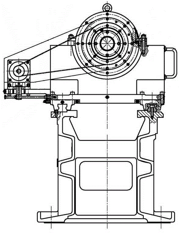
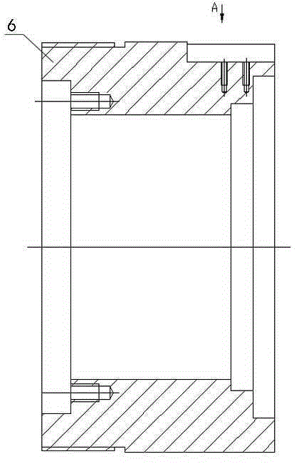
[0023] The deep hole processing cutter bar vibration damping supporter includes the front bearing seat 29, the outer contour of the front bearing seat 29 is cylindrical, one end is provided with a connecting flange, and the front bearing seat 29 has a three-stage stepped shaft hole. The first deep groove ball bearing 30 is embedded in the inner bottom of the large-diameter hole of the front bearing seat of the shaft hole, which is not connected to the flange end. The first deep groove ball bearing 30 is sleeved with a pulley connecting shaft 5, and the pulley connecting shaft 5 is provided with a shaft. The outer convex ring 32 is provided at one end of the hole, and the outer convex ring 32 extends to the lower part 30 of the first deep groove ball bearing (that is, in the middle diameter hole of the three-stage stepped shaft hole of the front bearing seat), and the pulley connecting shaft 5 The end face of the other end (that is, the non-external convex ring end) is fixed wit...
PUM
Abstract
The invention relates to a deep hole machine tool, in particular to a cutter bar vibration reducing supporter for the deep hole machine tool, and in particular, discloses a vibration reducing supporter of a deep hole machining cutter bar. The invention solves the problems of complex structure, no reasonability and weak vibration reducing effect in a traditional vibration reducing supporter of deep hole machining cutter bar. The vibration reducing support consists of left and right two parts, wherein the left part comprises a front bearing base, a belt wheel connecting shaft, a large synchronous belt wheel, a thread shaft, a pressure sleeve, a thrust bearing positioning sleeve and a thrust ball bearing; the right part comprises a back bearing base, an inner taper sleeve, a taper block, a taper block and a damping block uniformly distributed with axial wedge gaps, a spring base, a spring and a return ring; and axles of the front bearing base, the belt wheel connecting shaft, the thread shaft, the thrust bearing positioning sleeve, the pressure sleeve, the large synchronous belt wheel, the back bearing base, the inner taper sleeve, the taper block, the damping block, the return spring and the spring base are all positioned on one straight line. The vibration reducing supporter can fully realize the support and the vibration reduction of the deep hole machining cutter bar, is prominent in vibration reducing effect, and greatly improves the machining quality of deep hole parts.
Description
technical field [0001] The invention relates to a deep-hole machine tool, in particular to a cutter bar vibration-damping supporter used on the deep-hole machine tool, in particular to a tool-bar vibration-damping supporter for deep hole processing. Background technique [0002] In the field of mechanical processing, hole processing with a depth / aperture ratio greater than 5 is generally called deep hole processing. In conventional deep hole processing, processing methods such as a deep hole drilling system, a BTA (Boring and Trepanning Association: deep hole processing) system, or an injection system have been used. However, in deep-hole machining, the tool holder is long and has a relatively large major diameter, so it is difficult to perform high-precision deep-hole machining due to bending or buckling of the tool holder, rotational vibration during installation, and the like. After research, it is found that the deep hole drilling system in deep hole processing mainly p...
Claims
Application Information
Patent Timeline
Application Date:The date an application was filed.
Publication Date:The date a patent or application was officially published.
First Publication Date:The earliest publication date of a patent with the same application number.
Issue Date:Publication date of the patent grant document.
PCT Entry Date:The Entry date of PCT National Phase.
Estimated Expiry Date:The statutory expiry date of a patent right according to the Patent Law, and it is the longest term of protection that the patent right can achieve without the termination of the patent right due to other reasons(Term extension factor has been taken into account ).
Invalid Date:Actual expiry date is based on effective date or publication date of legal transaction data of invalid patent.