Eureka AIR delivers breakthrough ideas for toughest innovation challenges, trusted by R&D personnel around the world.

Power supply allocation network based on plane S-type bridge electromagnetic band-gap structures

A technology of electromagnetic bandgap structure and power distribution network, which is applied in the fields of electromagnetic fields, microwaves, and high-speed circuits, can solve problems such as poor synchronous switching noise suppression ability and poor power integrity, and achieve good power integrity and good suppression ability.

Active Publication Date: 2015-12-30
ZHEJIANG UNIV OF TECH
View PDF2 Cites 7 Cited by
  • Summary
  • Abstract
  • Description
  • Claims
  • Application Information

AI Technical Summary

Problems solved by technology

[0006] In order to overcome the deficiencies of poor synchronous switching noise suppression ability and poor power integrity in the wide frequency range of the existing power distribution network, the present invention provides a synchronous switching noise suppression ability in a wide frequency range and good power integrity. Good Power Distribution Network Based on Planar S-Bridge Electromagnetic Bandgap Structure

Method used


Image

  • Power supply allocation network based on plane S-type bridge electromagnetic band-gap structures
  • Power supply allocation network based on plane S-type bridge electromagnetic band-gap structures
  • Power supply allocation network based on plane S-type bridge electromagnetic band-gap structures

Examples


Embodiment Construction

[0017] The present invention will be further described below in conjunction with the accompanying drawings.

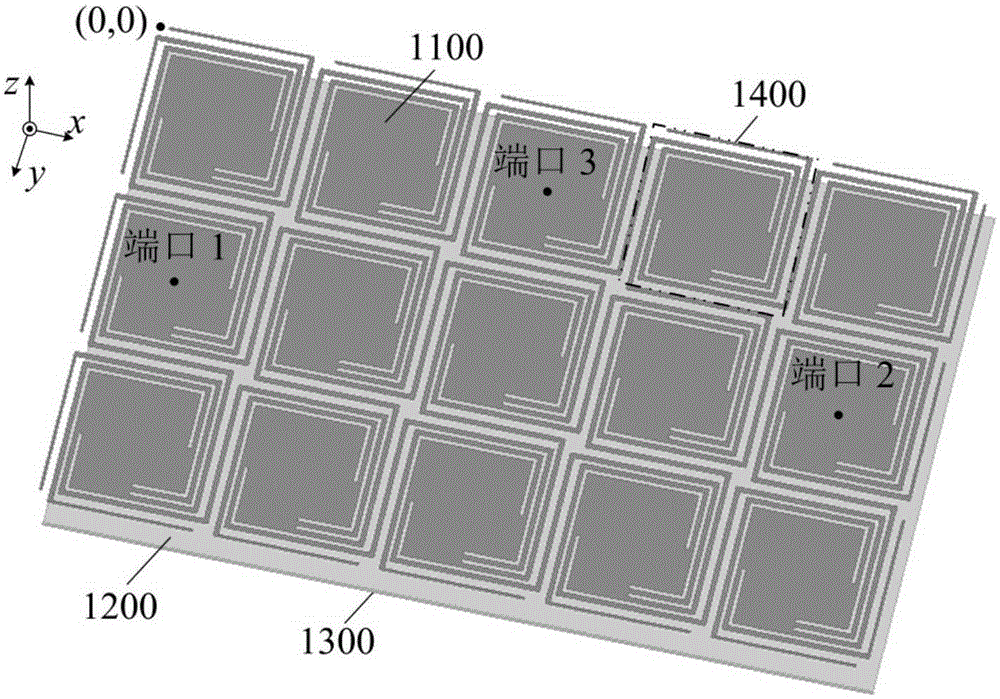
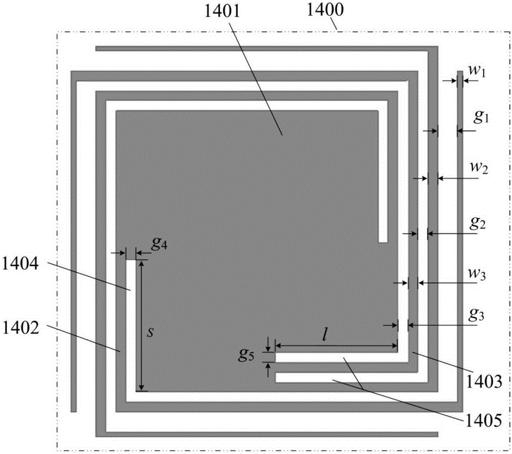
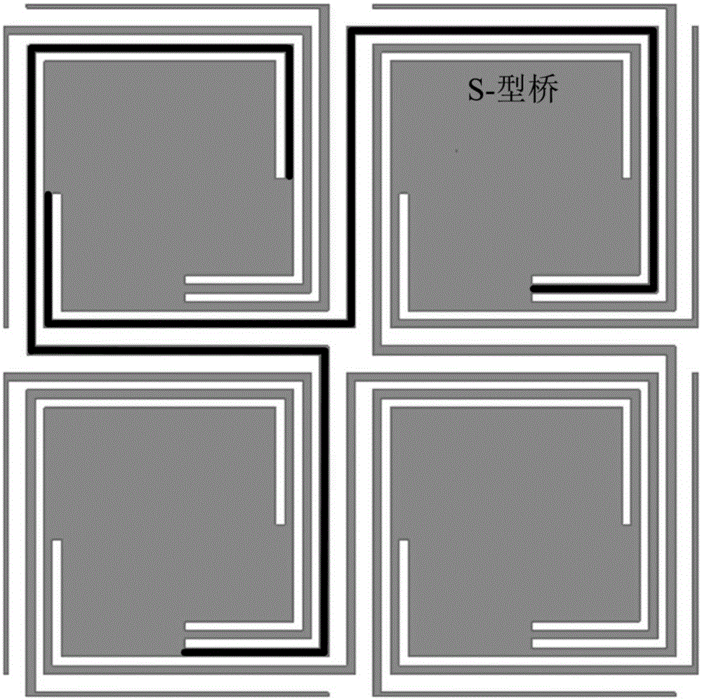
[0018] refer to Figure 1 ~ Figure 4 , a power distribution network based on a planar S-bridge electromagnetic bandgap structure, including a power plane 1100, a dielectric substrate 1200 and a ground plane 1300, the dielectric substrate covers the ground plane, and the power supply plane is located on the dielectric substrate In addition, the power distribution network further includes a planar S-bridge electromagnetic bandgap structure unit 1400, which is formed by periodic extension on the two-dimensional plane where the power supply plane is located. Matrix, each planar S-bridge electromagnetic bandgap structural unit includes a patch 1401 and four half S-bridges, the connection between the patch and the half S-bridge forms a slit by slotting, and the four One and a half S-shaped bridges are respectively provided with four lead-out ends located at the upper, lower...


PUM


Abstract

The invention provides a power supply allocation network based on plane S-type bridge electromagnetic band-gap structures. The power supply allocation network comprises a power supply plane, a dielectric substrate and a ground plane. The dielectric substrate covers the ground plane. The power supply plane is arranged on the dielectric substrate. Plane S-type bridge electromagnetic band-gap structure units periodically extend on a two-dimensional plane on which the power supply plane is positioned so that a matrix is formed. Each plane S-type bridge electromagnetic band-gap structure unit comprises a patch and four half S-type bridges. The connecting parts of the patch and the half S-type bridges are provided with slots so that slits are formed. The four half S-type bridges are respectively provided with four lead-out ends which are arranged at the upper, lower, left and right parts of the whole structure unit. The four lead-out ends of one plane S-type bridge electromagnetic band-gap structure unit are respectively connected with one of the lead-out ends of the upper, lower, left and right adjacent plane S-type bridge electromagnetic band-gap structure units so that a plane S-type bridge is formed. The power supply allocation network based on the plane S-type bridge electromagnetic band-gap structures has great simultaneous switching noise suppression capacity within wide frequency range and has great power supply integrity.

Description

technical field [0001] The invention relates to the technical fields of high-speed circuits, electromagnetic fields and microwaves, in particular to a power distribution network based on a planar S-bridge electromagnetic bandgap structure, especially a power distribution for solving the problem of synchronous switching noise suppression of modern high-speed digital circuits The internet. Background technique [0002] With the development of modern digital communication systems, the integration of the system is constantly improving. At the same time, in order to meet the requirements of high speed and low power consumption of the system, the edge of the high-speed clock signal is constantly becoming steeper, and the signal voltage is constantly decreasing. The simultaneous switching noise (Simultaneous Switching Noise, SSN) generated by a large number of high-speed switching devices in the working process of the high-speed circuit system, also known as the ground bounce noise...

Claims


Application Information

Patent Timeline
Patent Type & Authority Applications(China)
IPC IPC(8): H02M1/44
Inventor 陈朋廖立科姜立金礼聪党源杰
Owner ZHEJIANG UNIV OF TECH
Why Eureka
Eureka Blog
Learn More