
Light-expanding imaging device for eliminating moire of LED display screen

A technology of LED display screen and moiré pattern, which is applied in the direction of identification devices, diffusion elements, instruments, etc., and can solve the problems of easy damage to the eyes, poor viewing effect, dazzling, etc.

Inactive Publication Date: 2015-12-30
厦门科安技术开发有限公司
View PDF9 Cites 6 Cited by
  • Summary
  • Abstract
  • Description
  • Claims
  • Application Information

AI Technical Summary

Problems solved by technology

There are still two serious problems in the use of LED display screens: first, it is dazzling and dazzling when viewed at close range, the viewing effect is poor, and the eyes are easily damaged; second, the moiré interference phenomenon that occurs when shooting with digital cameras or digital cameras

Method used


Image

  • Light-expanding imaging device for eliminating moire of LED display screen
  • Light-expanding imaging device for eliminating moire of LED display screen
  • Light-expanding imaging device for eliminating moire of LED display screen

Examples


Embodiment Construction

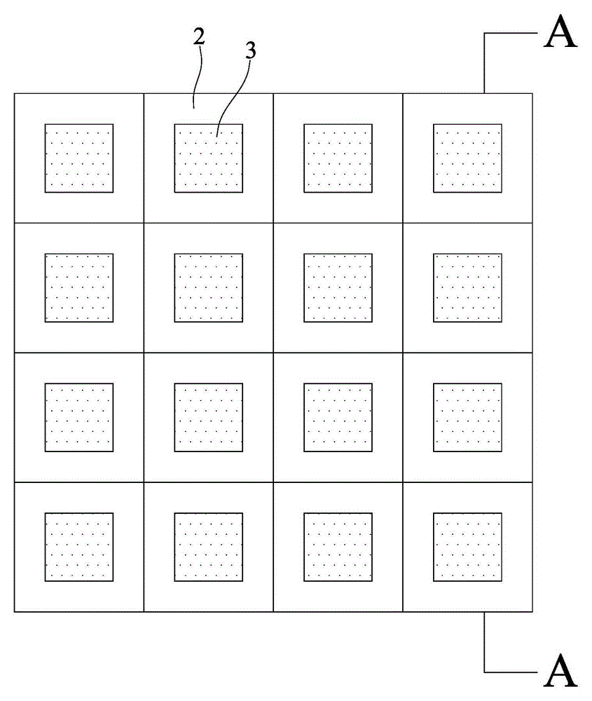
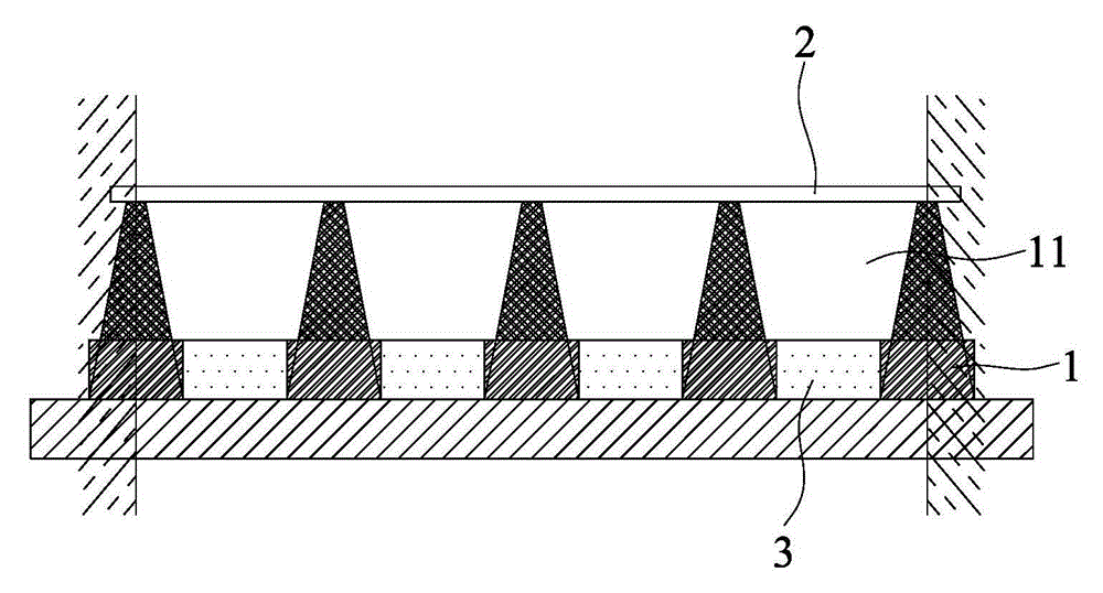
[0019] Such as figure 1 , figure 2 Shown is the first embodiment of a light-expanding imaging device for eliminating moiré on an LED display screen of the present invention, which is composed of a mask bottom plate 1 and a dielectric plate 2 .

[0020] The mask bottom plate 1 has a plurality of light guide cavities 11, the light guide cavities 11 are arranged in a regular shape, and the distance between each light guide cavity 11 is the LED lamp distance; the light guide cavities 11 are square in cross section The inverted cone hole, the height of the light guide cavity 11 is the LED lamp distance times to 2 times, the side wall inclination angle ɑ is 45-60 degrees, and the inclination angle ɑ can be adjusted to 10 degrees. An LED wick (point light source) 3 is installed at the bottom of the light guide cavity 11 .

[0021] The medium plate 2 is a flat plate, which is a light-diffusing imaging medium plate, a medium plate made of a transparent light-diffusing material or ...


PUM


Abstract

The invention discloses a light-expanding imaging device for eliminating moire of an LED (Light Emitting Diode) display screen. The light-expanding imaging device comprises a mask base plate and a light-expanding imaging dielectric slab, wherein the mask base plate is provided with a plurality of light-conducting cavities; the light-conducting cavities are arranged as back tapered holes with square cross sections; point light sources are arranged at the bottom of the light-conducting cavities; the light-expanding imaging dielectric slab is covered on the top surfaces of the light-conducting cavities of the mask base plate; the LED display screen is totally covered by the light-expanding imaging device provided by the invention, so that the point light sources can be turned into area light sources after the light emitted from the luminous points is subjected to the treatment, such as, the light conduction of the light-conducting cavities, the light emission of the walls of the light-conducting cavities, the light absorption, light filtering, color mixing and scattering of the light-expanding imaging dielectric slab, and the like, after the LED display screen is lightened; the luminous points are imaged on the surface of the light-expanding imaging dielectric slab after the light conduction of the light-conducting cavities, the light radiation of the walls of the light-conducting cavities and the color mixing treatment and scattering of the light-expanding imaging dielectric slab, the continuous light is formed, the grid structure and the granular sensation of the luminous points are eliminated, the moire generating conditions of a digital video (or camera) and the LED display screen are eliminated and the effect of eliminating the moire is good.

Description

technical field [0001] The invention relates to an optical device, in particular to a light-diffusing imaging device for an LED display screen that improves the imaging effect of an LED display screen and eliminates moiré patterns on the LED display screen. Background technique [0002] As a rapidly developing display medium, LED display has been widely used in various industries. Especially as a video display, the LED display screen has become the first choice of the majority of users for the image promotion of enterprises and institutions and the release of information in public places with its modern attitude. There are still two serious problems in the use of LED display screens: firstly, it is dazzling and dazzling when viewed at close range, the viewing effect is poor, and the eyes are easy to be damaged; secondly, moiré interference occurs when digital cameras or digital video cameras are shot. Moiré refers to irregular interference fringes that appear on the photose...

Claims


Application Information

Patent Timeline
Patent Type & Authority Applications(China)
IPC IPC(8): G09F9/33G02B5/02
CPCG09F9/33G02B5/02
Inventor 庄偲浛
Owner 厦门科安技术开发有限公司
Learn More