Suspended unbalanced dynamic tension sensor

A tension sensor and unbalanced technology, applied in the field of sensing, can solve the problems of complex installation and disassembly, uneven force transmission, cumbersome, etc., and achieve the effect of ensuring measurement stability, convenient disassembly and installation, and simple overall structure

Inactive Publication Date: 2015-12-30
NANJING UNIV OF AERONAUTICS & ASTRONAUTICS
View PDF10 Cites 5 Cited by
  • Summary
  • Abstract
  • Description
  • Claims
  • Application Information

AI Technical Summary

Problems solved by technology

Although they have a series of products to choose from for different objects, they have the advantages of high precision, small temperature drift, and fast response, but they still have the following disadvantages: First, these products are mainly suitable for static measurement, without taking into account the rope Under the action of instantaneous large tension, it is affected by friction force; secondly, for the measurement object is a wide flat belt-like structure such as a seat belt, in order to prevent the rope from falling off and making the measurement invalid, the installation and disassembly of the above products are not only complicated, but also Every disassembly and assembly requires tedious calibration by professionals before it can be put into use. This type of sensor is rarely reused in the actual experiment process, which greatly increases the cost; in addition, taking the EL20-S458 of MEAS in the United States as an example, For a wide flat belt-like structure, a balanced structure on both sides is often used to fix the rope. The default force on the rope is uniform. However, in the actual measurement process, the twisting of the rope may make the The uneven tension, especially in the dynamic measurement process, makes the situation more complicated, which leads to the uneven force transmission of the rope acting on the specimen, so that this type of structure cannot realize dynamic measurement.

Method used


Image

  • Suspended unbalanced dynamic tension sensor
  • Suspended unbalanced dynamic tension sensor
  • Suspended unbalanced dynamic tension sensor

Examples


Embodiment Construction

[0043] Below in conjunction with accompanying drawing, technical scheme of the present invention is described in further detail:

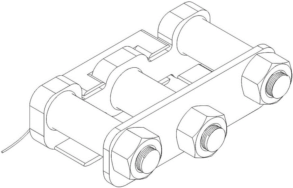
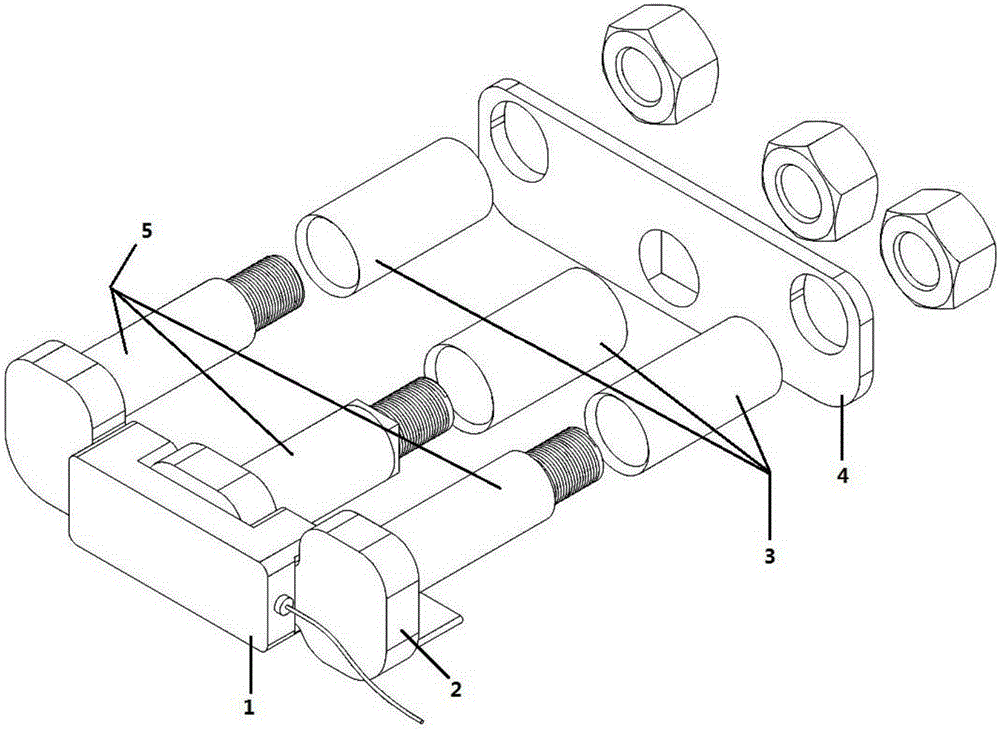
[0044] The invention discloses a suspension type unbalanced dynamic tension sensor, which comprises a three-axis force-bearing body, a baffle plate, first to third nuts, first to third rollers, first to fourth strain gauges, and a rope and electrical boxes;

[0045] The triaxial force-bearing body includes a force-bearing base plate and first to third force-conducting cylinders;

[0046]The first to third rollers are chamfering rollers;

[0047] The first force-guiding cylinder and the third force-guiding cylinder are vertically arranged at both ends of the force-bearing base plate, the second force-guiding cylinder is vertically set in the middle of the force-bearing base plate, and the first to third force-guiding cylinders Chamfers corresponding to the first to third rollers are respectively provided between the stressed bottom plate;

[0048...


PUM


Abstract

The invention discloses a suspended unbalanced dynamic tension sensor. Through double cantilever beam structures and by adopting strain gauges for indirect measurement and roller design, the friction can be reduced during instant large tension measurement, and the phenomenon that a measured rope belt is burnt after being heated is effectively prevented; in addition, the unbalanced suspended structural design is adopted, so that the suspended unbalanced dynamic tension sensor is not required to be fixed on a base during measurement, on one hand, the fact that the rope belt doses not fall off to avoid measurement failure during a measuring process is guaranteed, and on the other hand, bad influences of non-uniform force during dynamic measurement are eliminated effectively and the accuracy during dynamic measurement is ensured.

Description

technical field [0001] The invention relates to the field of sensor technology, in particular to a suspension type unbalanced dynamic tension sensor. Background technique [0002] The tension sensor, also called the tension detector, is an instrument used to measure the tension value of the coil during the tension control process. Strain gauge is an important sensing element and plays a very important role in dynamic mechanical measurement. Among them, strain gauge technology is the most widely used and most mature measurement technology so far. The strain gauge sensing technology utilizes the resistance strain effect of the metal to paste the strain gauge on the test piece. The resistance value of the metal will change with the mechanical deformation, and the change of resistance reflects the strain value of the pasted part of the strain gauge. . This testing method has its unique advantages: [0003] 1. Simple structure and small size; [0004] 2. The conversion circui...

Claims


Application Information

Patent Timeline
IPC IPC(8): G01L1/22
Inventor 马敏毓赵敏王冬月赵志豪蔡力炯
Owner NANJING UNIV OF AERONAUTICS & ASTRONAUTICS
Why Eureka
Try Eureka