A method and device for testing the stiffness of an anti-roll torsion bar for a rail vehicle

A technology of anti-rolling torsion bar and test device, which is applied in the direction of measuring device, elastic test, machine/structural component test, etc. It can solve the problems of fixed installation center distance, unknown torsion bar loading, and difficult movement of equipment, etc. , to achieve the effect of convenient maintenance and repair, reduced test cost, and short test time for a single piece

Active Publication Date: 2019-09-17
ZHUZHOU TIMES NEW MATERIALS TECH
View PDF7 Cites 0 Cited by
  • Summary
  • Abstract
  • Description
  • Claims
  • Application Information

AI Technical Summary

Problems solved by technology

[0007] The above-mentioned patents are some technical solutions declared by the applicant before, but there are still some problems. For example, in the solution of CN201520344577.4, the installation center distance of this structure is fixed, which cannot be universally applied to the stiffness of torsion bars of various shapes and models. test, and it is not known how to provide strong support for the loading cylinder when loading, so it is not known how to load the torsion bar; and the scheme CN200820158556.3 has a complex structure, the equipment is not easy to move, and the test time is long, so the operation and maintenance higher cost

Method used


Image

  • A method and device for testing the stiffness of an anti-roll torsion bar for a rail vehicle
  • A method and device for testing the stiffness of an anti-roll torsion bar for a rail vehicle
  • A method and device for testing the stiffness of an anti-roll torsion bar for a rail vehicle

Examples


Embodiment 1

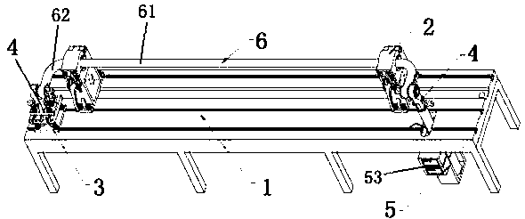
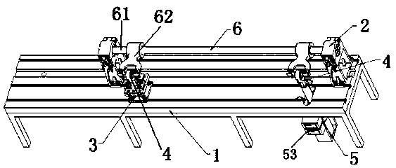
[0045] Such as Figure 1-Figure 10 As shown, a rail vehicle anti-rolling torsion bar stiffness test device includes a support module 1, a clamping module 2, a fixed module 3, a connecting module 4 and a load measurement module 5, wherein the clamping module 2 and the connecting module 4 are each There are two, the clamping module 2 and the fixing module 3 can be slidably arranged on the support module 1, the clamping module 2 is used to fix the torsion bar shaft 61, and a connecting module 4 is detachably connected above the fixing module 3 through one end , the other end is used to connect with the torsion arm 62 at the non-loading end, one end of the other connection module 4 is detachably connected with the loading measurement module 5, and the other end is used to connect with the torsion arm 62 at the loading end.

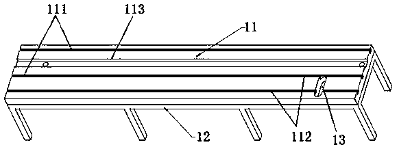
[0046] The support module 1 includes a bracket 12 and a base plate 11, the base plate 11 is arranged on the upper end of the bracket 12, the bracket 12 provid...

Embodiment 2

[0058] The difference between this embodiment and the first embodiment is that the cover plate 22 and the base 21 of the clamping module 2 are separated, and both ends of the cover plate 22 and the base 21 can be fixed by a locking device 23 . For example, two hasps are provided on the base 21 , and the cover plate 22 is loosened or fixed on the base 21 through the opening and closing of the two hasps.

Embodiment 3

[0060] The difference between this embodiment and the first embodiment is that the connection structure one 411 of the connecting rod 41 is a flat plate protruding downwards, and there is a pin hole for fixing with the fixed module 3 or the load measurement module 5 in the middle of the flat plate One 412, there is a pluggable quick latch 413 in the pin hole one 412.

[0061]The connecting structure three 331 of the connecting seat 33 is that there are two upwardly protruding flat plates in the middle of the connecting seat 11, and there is a pin hole three 332 for fixing with the connecting module 4 in the middle of the two flat plates, and between the two flat plates The distance is equal to the thickness of the flat plate where the connecting rod 41 protrudes downward.

[0062] The connection structure 2 521 of the loading connecting mandrel 52 is that there are two upwardly protruding flat plates above the loading connecting mandrel 52, and a pin hole 2 522 for fixing with...


PUM


Abstract

The invention relates to an anti-side-rolling torsion bar rigidity testing method and apparatus for rail vehicles. The anti-side-rolling torsion bar rigidity testing method for rail vehicles is implemented by installing a torsion bar in the anti-side-rolling torsion bar rigidity testing apparatus for rail vehicles, that is, the anti-side-rolling torsion bar rigidity testing method for rail vehicles includes the following steps: fixing the torsion bar through a clamping module of the testing apparatus, connecting a non-loading end of a torsion arm to a fixing module of the testing apparatus through a connection module of the testing apparatus for fixing, connecting a loading end of the torsion arm to a loading measuring module of the testing apparatus through the connection module, loadingthe torsion bar by means of the loading measuring module, and obtaining the rigidity value of the torsion bar according to displacement and load. For the anti-side-rolling torsion bar rigidity testingmethod s for rail vehicles, through modularized design of the testing apparatus, a plurality of modules are general; and the connection module is designed with a plurality of models according to thedemands of different torsion bars, so that when rigidity testing is performed on different torsion bars, testing of rigidity of various torsion bars with different shape can be realized only by exchanging the connection module with the corresponding model according to the specification of the torsion bar. Therefore, the anti-side-rolling torsion bar rigidity testing apparatus for rail vehicles hashigh universality and can reduce the test cost.

Description

technical field [0001] The invention relates to a stiffness test method and device, in particular to a stiffness test method and device for an anti-rolling torsion bar for a rail vehicle, and belongs to the technical field of locomotive detection. Background technique [0002] The anti-roll torsion bar is an important safety component to prevent the car body from rolling when the rail vehicle passes through a curve. When the car body rolls, the two connecting rods of the anti-roll torsion bar move in the opposite direction, and one Up, a connecting rod is down, the torsion bar bearing is subjected to combined bending and torsion loads, and deforms, and its elastic reaction moment resists the side roll of the car body. The stiffness of the torsion bar reflects the strength of the elasticity, directly affects the roll angle of the car body, and indirectly affects the comfort of the passengers, and requires a stiffness performance test before it is put into use. [0003] At pr...

Claims


Application Information

Patent Timeline
Patent Type & Authority Patents(China)
IPC IPC(8): G01M5/00
Inventor 谭秋平陈军韩喜龙王小臣陈晓兵徐向阳朱杰辉黄承坤
Owner ZHUZHOU TIMES NEW MATERIALS TECH
Why Eureka
Try Eureka