Parallel hydraulic retarder with clutch device and separation method thereof
A hydraulic retarder, clutch device technology, applied in the direction of liquid resistance brakes, brake types, brake components, etc., can solve the problem that idling loss can not be completely eliminated, to reduce its own weight, reduce complexity, simplify the internal structure effect
- Summary
- Abstract
- Description
- Claims
- Application Information
AI Technical Summary
Problems solved by technology
Method used
Image

Examples
specific Embodiment approach 1
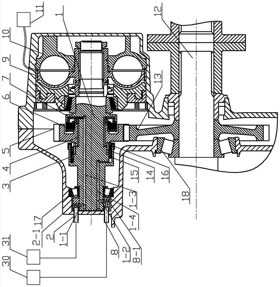
[0017] Specific implementation mode one: combine figure 1 Describe this embodiment, a parallel hydraulic retarder with a clutch device and its separation method, which includes a brake shaft 1, a first control system 2, a sleeve clutch 3, a speed-up gear shaft 4, a speed-up gear 5. Friction clutch 6, friction clutch actuator 7, second control system 8, hydraulic retarder rotor 9, stator 10, hydraulic retarder control liquid filling mechanism 11, gearbox output shaft 12, transmission gear 13, The brake shaft bearing 17, the transmission output shaft bearing 18, the first control valve 31, the second control valve 30 and the housing; the brake shaft 1 is horizontally and fixedly installed in the housing, and the first control valve 31 and the first control system 2 connection, the second control valve 30 is connected with the second control system 8, the first control system 2 and the second control system 8 are fixedly installed on the outer circular surface of the left end of ...
specific Embodiment approach 2
[0019] Specific implementation mode two: combination figure 1 Describe this embodiment, a parallel hydraulic retarder with a clutch device and its separation method in this embodiment, the friction clutch 6 is a multi-plate friction clutch, and the engagement of the multi-plate friction clutch is controlled by a hydraulic spool or separate, and other structures are the same as in Embodiment 1.
[0020] In this embodiment, after the control system of the hydraulic retarder receives the signal of canceling the braking retardation, the control system 11 first discharges the working medium in the working chamber of the hydraulic retarder back to the fuel tank, and then the gear coupling The pressure oil of the actuator actuator 15 is released, and the gear coupling 16 is returned to the initial separation position under the action of the return spring 14, and the separation of the hydraulic retarder and the transmission shaft 12 of the transmission is completed.
specific Embodiment approach 3
[0021] Specific implementation mode three: combination figure 1 Describe this embodiment, a parallel hydraulic retarder with a clutch device and its separation method in this embodiment, the sleeve clutch pressure cylinder 3 includes a return spring 14, a sleeve coupling actuator 15 and a sleeve The gear coupling 16, the sleeve gear coupling actuator 15 is set on the sleeve gear coupling 16, the return spring 14 is sleeved on the sleeve gear coupling actuator 15, the brake shaft 1 and the speed-up gear 5 are respectively The arc-shaped external teeth matched with the internal teeth on the internal tooth sleeve 16 are processed, and the other structures are the same as those in Embodiment 1.
PUM
 Abstract
Description
Claims
Application Information
 - R&D
- Intellectual Property
- Life Sciences
- Materials
- Tech Scout
- Unparalleled Data Quality
- Higher Quality Content
- 60% Fewer Hallucinations
Browse by: Latest US Patents, China's latest patents, Technical Efficacy Thesaurus, Application Domain, Technology Topic, Popular Technical Reports.
© 2025 PatSnap. All rights reserved.Legal|Privacy policy|Modern Slavery Act Transparency Statement|Sitemap|About US| Contact US: help@patsnap.com