Tooling and method for slantly lifting piston assembly

A piston component and tooling technology, applied in the direction of load hanging components, transportation and packaging, etc., can solve the problems of inability to use lifting tooling, lifting piston components, and lifting heights that cannot meet the aforementioned requirements, and achieve low manufacturing costs and methods Easy operation and strong versatility

Active Publication Date: 2015-12-30
CSSC MARINE POWER
View PDF7 Cites 3 Cited by
  • Summary
  • Abstract
  • Description
  • Claims
  • Application Information

AI Technical Summary

Problems solved by technology

The existing lifting tooling and method for the piston assembly of the marine diesel engine are as follows: use a special piston lifting tool to directly lift the piston assembly out of the marine diesel engine vertically, because this method has certain restrictions on the lifting height of the piston assembly, that is, the engine room on the top of the ship engine room The lifting height of the crane should be at least greater than or equal to the vertical height of the piston assembly. When the lifting height of the crane in the engine room does not meet the aforementioned requirements, the aforementioned lifting tools and methods cannot be used to lift the piston assembly

Method used


Image

  • Tooling and method for slantly lifting piston assembly
  • Tooling and method for slantly lifting piston assembly
  • Tooling and method for slantly lifting piston assembly

Examples


Embodiment Construction

[0029] The present invention will be further described below in conjunction with drawings and embodiments.

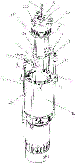
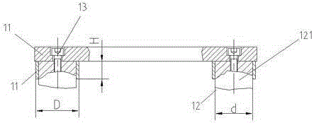
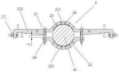
[0030] Such as Figure 1 ~ Figure 4 As shown, the present invention includes a pair of horizontal plates 1, a piston rod clamp ring set 2 and an upper beam 3, the two ends of the lower surface of the horizontal plate 1 are vertically welded to the circular tube 11 respectively, and the height H of the circular tube is less than the outer diameter D of the circular tube. The inner diameter d of the circular tube contains the outer diameter of the upper end of the cylinder head stud 121, and the two ends of the horizontal plate 1 are fixedly connected to the upper end of the cylinder head stud 12 inserted into the circular tube 11 by the fastening screw 13 to form a goal-shaped frame. Such a structure makes the connection between the transverse plate 1 and the cylinder head stud 12 firm, and can prevent the fastening screw 13 from being subjected to shearing force.

[00...


PUM


Abstract

The invention discloses a tooling and method for slantly lifting a piston assembly, comprising a pair of transverse plates, a piston rod grip ring group and an upper beam, wherein the piston rod grip ring group comprises a main pipe clamp, an auxiliary pipe clamp, two arc-shaped bushes, a plurality of struts and shackles, and chains with hooks; the arc-shaped bushes at the inner sides of the main pipe clamp and the auxiliary pipe clamp are used for clamping the upper part of a piston rod; when a piston assembly is slantly lifted, two ends of the upper beam are connected with the two ends of the main pipe clamp respectively by virtue of the chains with the hooks and the shackles; and a hook at the lower side of an engine-room crane is used for hooking the middle part of the upper beam. A method for slantly lifting the piston assembly disclosed by the invention comprises the steps that vertically lifting the piston assembly is vertically lifted and supported on the transverse plates, and the suspension center is dropped to the upper part of the piston rod, thus realizing the purpose of slantly lifting the piston assembly. The tooling disclosed by the invention is strong in universality, low in manufacture cost, simple and convenient to operate, and the problem that slant lifting needs of multiple diesel engine piston assemblies for ships are met through adoption of arc-shaped bushes of various specifications and struts is solved.

Description

technical field [0001] The invention relates to a lifting tool for a piston assembly of a marine diesel engine, in particular to a lifting tool and a method for obliquely lifting a piston assembly out of a main cylinder liner of a marine diesel engine, and belongs to the technical field of special lifting tools. Background technique [0002] The piston assembly is one of the main moving parts of the diesel engine and an important part of the combustion chamber. During the operation of the diesel engine, if there are problems such as wear, cracks and top ablation of the piston components in the cylinder, it will have a very bad impact on the working performance and service life of the diesel engine. Therefore, it is always necessary to ensure that the piston components of each cylinder are Good condition is very necessary. [0003] During the service period of the marine diesel engine, it is necessary to lift the piston assembly out of the marine diesel engine for related ma...

Claims


Application Information

Patent Timeline
IPC IPC(8): B66C1/14B66C13/04
Inventor 唐艾飞李正刚朱二桥鲍爱红
Owner CSSC MARINE POWER
Why Eureka
Try Eureka