engine assembly table

A technology for assembly tables and engines, applied to workbenches, manufacturing tools, etc., can solve problems such as potential safety hazards, existence of production processes, failure of stoppers, etc., and achieve the effect of reducing potential safety hazards

Active Publication Date: 2017-07-28
ANHUI JIANGHUAI AUTOMOBILE GRP CORP LTD
View PDF8 Cites 0 Cited by
  • Summary
  • Abstract
  • Description
  • Claims
  • Application Information

AI Technical Summary

Problems solved by technology

[0004] The stopper in the prior art is driven by a cylinder, and the cylinder is controlled by the control mechanism of the production line. When an error occurs in the control mechanism or the cylinder, the stopper will fail, and there will be safety hazards in the production process.

Method used


Image

  • engine assembly table
  • engine assembly table
  • engine assembly table

Examples


Embodiment Construction

[0024] In order to enable those skilled in the art to better understand the technical solutions of the present invention, the present invention will be further described in detail below in conjunction with the accompanying drawings.

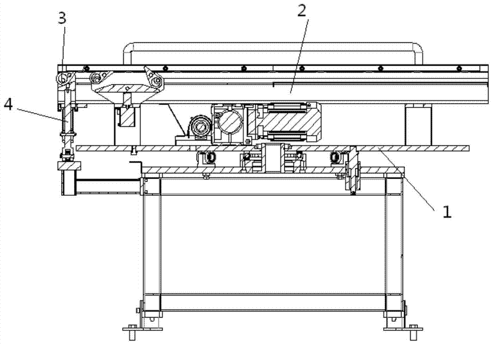
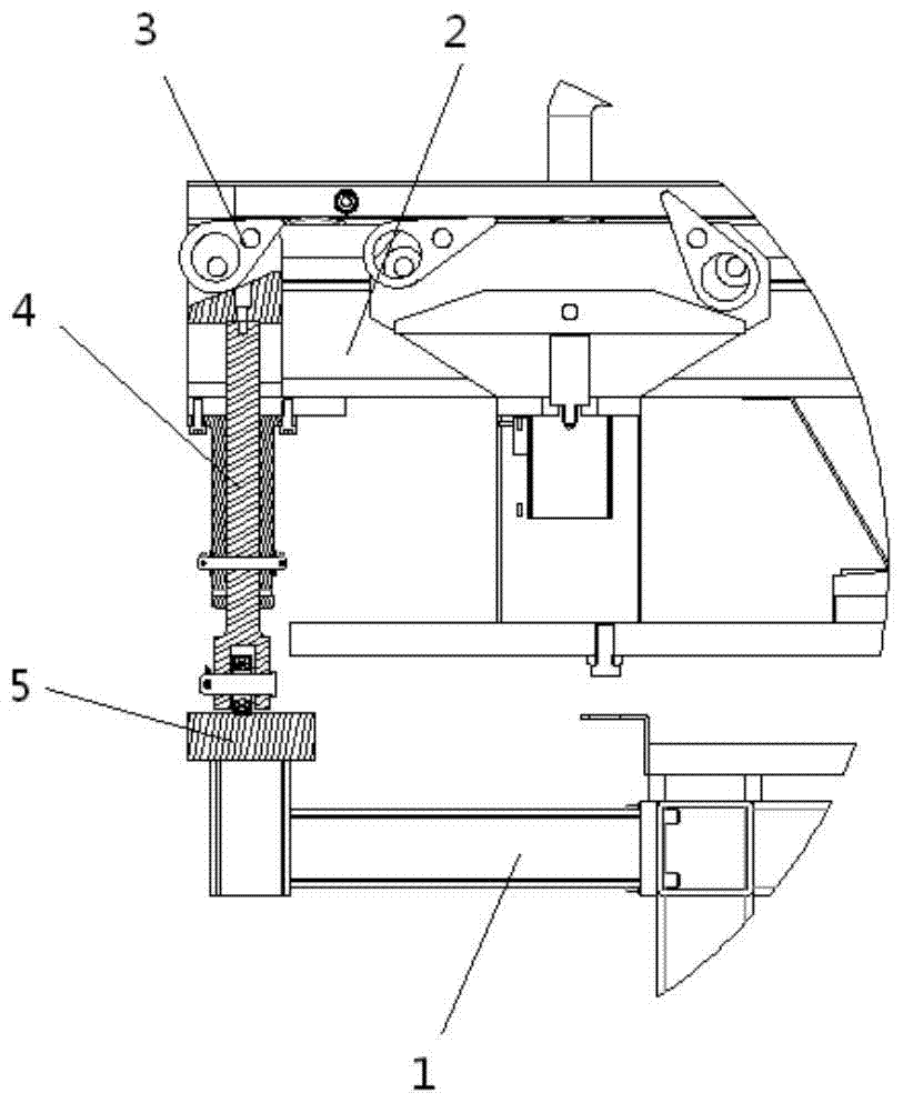
[0025] Such as Figure 1-5 As shown, an engine assembly platform provided by the embodiment of the present invention includes a base 1 and a turntable 2, and the turntable 2 is rotatably arranged on the top surface of the base 1, and also includes a cam 3, a sliding column 4 and a concave-convex Part 5, the cam 3 is rotatably connected to the turntable 2, the concave-convex part 5 is set on the base 1, the sliding column 4 is slidably connected to the rotary table 2, and the bottom end of the sliding column 4 is rollingly connected to the concave-convex surface of the concave-convex part 5 , the top of the sliding column 4 is a wedge 6, and the slope of the wedge 6 abuts the cam 3; on the rotation stroke of the cam 3, it has a position where the ...


PUM


Abstract

The invention discloses an engine assembly stand which comprises a base and a rotary table, wherein the rotary table is rotationally arranged on the base, the engine assembly stand further comprises a cam, a sliding column and a concave and convex part, wherein the cam is rotationally connected to the rotary table, the concave and convex part is arranged on the base, the sliding column is glidingly connected to the rotary table, the bottom end of the sliding column is connected to the concave and convex surface of the concave and convex part, the top end of the sliding column is a wedge, and the slope of the wedge abuts against the cam; on the turning trip of the cam, the cam has a position with one top end protruding out of the working surface of the rotary table and a position with one top end not protruding out of the working surface of the rotary table. According to the engine assembly stand, when the rotary table rotates on the base, the sliding column slides back and forth on the concave and convex surface, rising and lowering of the sliding column drive the cam to rotate so that the cam can or cannot protrude out of the rotary table, therefore, blocking and feeding work is finished, the structure is in sole mechanical transmission, and the probability of potential safety hazards caused by electrical accidents is reduced.

Description

technical field [0001] The invention relates to engine manufacturing technology, in particular to an engine assembly platform. Background technique [0002] The engine assembly table is used to assemble various parts during the engine assembly process. Generally, it includes a base and a rotatable turntable set on the base. When the engine is assembled, the finished product of the previous process is transferred to this machine through the production line On the rotary table of the process, the operator turns the rotary table to the processing position and performs the corresponding operation on the workpiece. [0003] In the whole processing flow of this process, the rotary table has two positions: circulation position and processing position. There is a feeding port on the rotary table. In the circulating position, the feeding port is docked with the production line to facilitate the circulation of workpieces; the circulating position After turning a certain angle, it is ...

Claims


Application Information

Patent Timeline
Patent Type & Authority Patents(China)
IPC IPC(8): B25H1/14B25H1/02
CPCB25H1/0007B25H1/02B25H1/14
Inventor 王东鑫
Owner ANHUI JIANGHUAI AUTOMOBILE GRP CORP LTD
Why Eureka
Try Eureka