Pneumatic positioning mechanism

A positioning mechanism and positioning claw technology, which is applied in metal processing, metal processing equipment, manufacturing tools, etc., can solve the problems of heavy workload and high error rate

Inactive Publication Date: 2015-12-30
WUXI QINGYANG MACHINERY MFG
View PDF6 Cites 0 Cited by
  • Summary
  • Abstract
  • Description
  • Claims
  • Application Information

AI Technical Summary

Problems solved by technology

Automated assembly: According to production requirements, staff need to perform various tasks such as debugging, inspection, and assembly of machinery. This work requires a large workload and a high error rate

Method used


Image

  • Pneumatic positioning mechanism
  • Pneumatic positioning mechanism

Examples


Embodiment 1

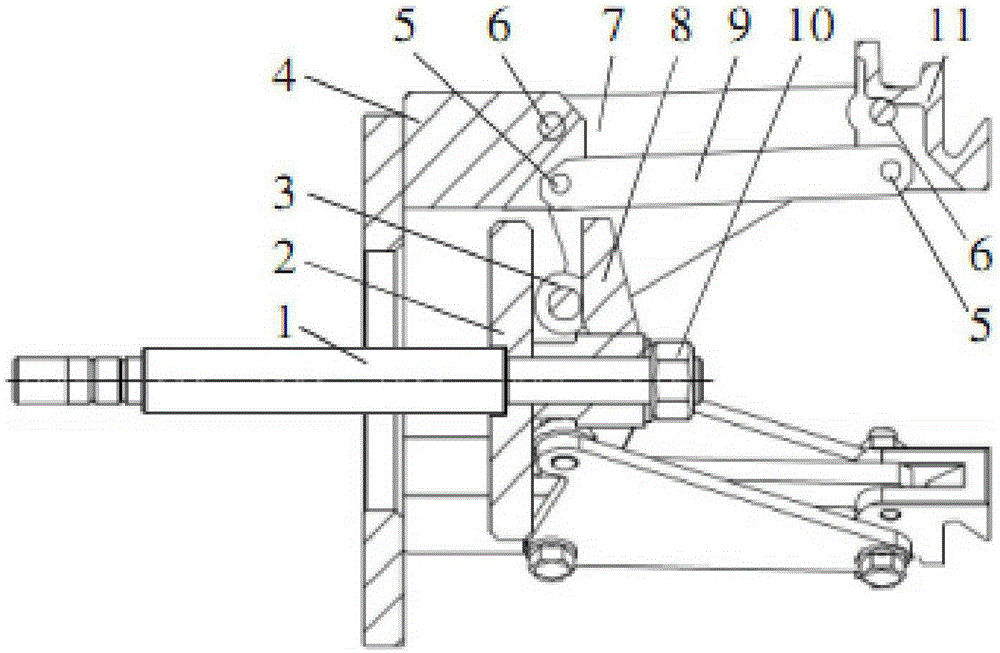
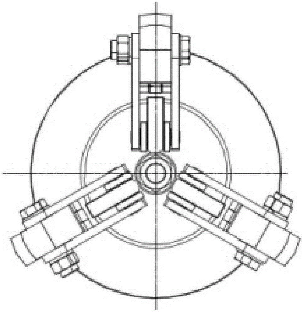
[0021] The triangular joint plate 2 is connected with the piston rod 1 of the pneumatic cylinder, and the triangular positioning frame 8 is fixed on the end of the pneumatic piston cylinder 1 through a positioning nut 10 . One end of the rib plate 7 is connected with the positioning claw base 4 through a cylindrical pin 6, and the two can rotate relatively. The two ends of the connecting frame 9 are respectively connected with the ribs 7 through pins 5 , and the positioning claws 11 are fixed on the connecting frame 9 and move along with the movement of the connecting frame 9 . The pneumatic piston rod 1 is connected with the pneumatic cylinder, and the opening and closing of the positioning claws are controlled through the telescopic movement of the pneumatic cylinder. 3 locating pawls 11 are evenly distributed on the circumference, as shown in Fig. figure 2 As shown, and the distance between two positioning claws is 120°. When the pneumatic cylinder drives the pneumatic p...


PUM


Abstract

The invention discloses a pneumatic positioning mechanism. A triangular joint plate is connected with an air cylinder plunger, and a triangular positioning frame is fixed on the tail end of an air pressure piston cylinder by virtue of a positioning nut. One end of a ribbed plate is connected with a positioning claw foundation support by virtue of a cylindrical pin, the ribbed plate and the positioning claw foundation support can rotate relatively, the other end of the ribbed plate is connected with a cylindrical roller, and the cylindrical roller is clamped between the triangular joint plate and the triangular positioning frame. Two ends of a connecting frame are respectively connected with the ribbed plate by virtue of a dowel, a positioning claw is fixed on the connecting frame, and the positioning claw can move along with the connecting frame. The air pressure plunger is connected with an air cylinder, and the opening and closing of the positioning claw are controlled by virtue of the telescopic movement of the air cylinder. Three positioning claws are uniformly distributed on the circumference, and an angle formed between every two adjacent positioning claws is 120 degrees.

Description

technical field [0001] The invention relates to the technical field of mechanical manufacturing and assembly, in particular to a pneumatic positioning mechanism. Background technique [0002] The development of mechanical automation technology provides a strong guarantee for improving productivity. Therefore, it can be said that mechanical automation technology is one of the most influential and economically valuable science and technology in the 20th century. It strongly promotes the development of people's production and life, and plays an important role in promoting the improvement of people's living standards. Therefore, in the process of my country's socialist construction and economic development, we must pay attention to the research and application of mechanical automation technology, and in the continuous practice and application, sum up experience and lessons, innovate mechanical automation technology, realize the automation development of my country's machinery ma...

Claims


Application Information

Patent Timeline
Patent Type & Authority Applications(China)
IPC IPC(8): B23P19/00
CPCB23P19/007B23P2700/50
Inventor 唐靖岚
Owner WUXI QINGYANG MACHINERY MFG
Why Eureka
Try Eureka