Shoe sole cleaning machine

A shoe sole cleaning machine and screw technology, applied in the field of cleaning appliances, can solve problems such as waste of manpower, material resources and financial resources, dirty soles, troubles, etc., and achieve the effects of energy saving, ingenious design, and convenient use

Inactive Publication Date: 2015-12-30
BEIJING TECHNOLOGY AND BUSINESS UNIVERSITY
View PDF5 Cites 3 Cited by
  • Summary
  • Abstract
  • Description
  • Claims
  • Application Information

AI Technical Summary

Problems solved by technology

However, people will inevitably bring dirt such as dust into the room through the soles of the shoes from outdoor to indoor, so that the indoor ground cannot be kept clean.
At present, in order to solve this problem, in large public places such as shopping malls, many cleaners keep cleaning the ground to keep the ground clean, causing a lot of waste of manpower, material resources and financial resources; in the dormitory, a piece of felt is placed outside It is quite troublesome for the family members to enter the house and change shoes, and it is even more embarrassing for the guests who come to the house to change shoes. The root cause is that the soles of the shoes are dirty. various countermeasures
In order to keep the indoor ground clean and hygienic, we have designed a sole cleaning machine that cleans the soles, which completely solves the problem of dirty soles before entering the room

Method used


Image

  • Shoe sole cleaning machine
  • Shoe sole cleaning machine
  • Shoe sole cleaning machine

Examples


Embodiment Construction

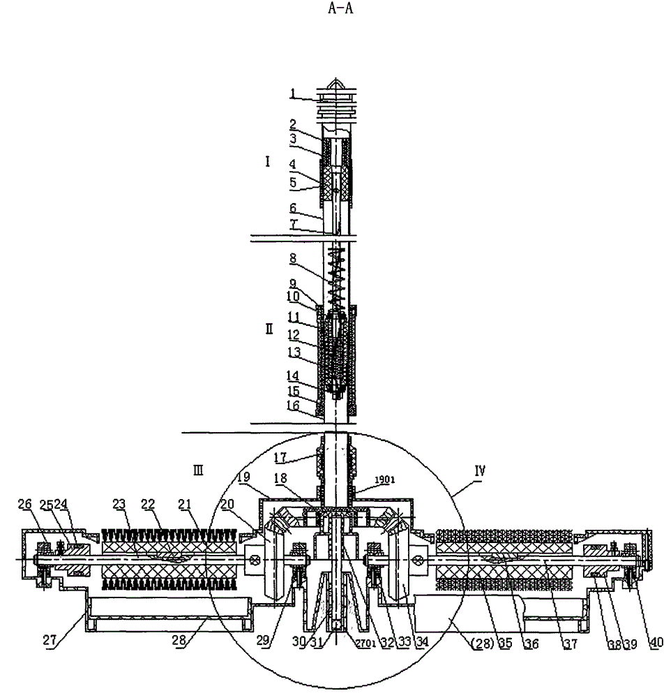
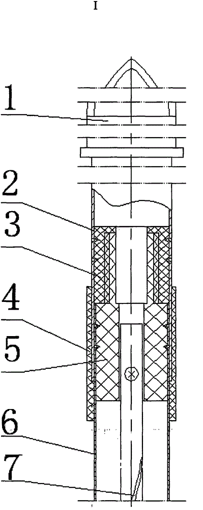
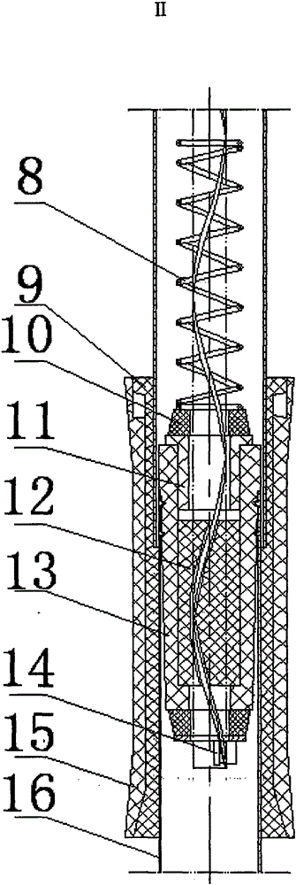
[0044] Figure 1 to Figure 3 Shown a preferred embodiment of the present invention, as shown in the figure, a kind of shoe sole cleaning machine of the present invention mainly is made of base, rotating shaft, main shaft body, bevel gear, roller brush and a screw rod mobile rotation device.

[0045] Base 27 is positioned at the lowermost end of this device, see figure 1 , Figure 1-04 , in the illustrated embodiment, the middle part is a conical cylinder that protrudes upwards, and there is a cylinder 2701 with a hole in the middle of the conical cylinder, leaving an installation space for installing the steel ball 31 and the main shaft body 32. A bearing 30 is installed in the cylinder 2701 .

[0046] On both sides of the middle part of the base 27, two pairs of left and right rear axles 23, right rear axles 37, left front axles 42, and right front axles 47 arranged in the same row, front and rear, are mounted on the base 27 by four pairs of bearing blocks respectively.

...


PUM


Abstract

A shoe sole cleaning machine comprises a base, a rotating shaft or a rotating shaft set, a main shaft body and a screw rod moving set and rotating device, wherein rotating shafts are fixedly installed on the base through bearing pack bases respectively, and at least one rotating shaft is sleeved with a bevel gear and a rolling brush; the shaft part of the main shaft body is inserted in a cylindrical hole in the middle of the base, and the bottom end of the main shaft body makes contact with a steel ball; the screw rod moving set and rotating device is arranged at the upper end of the main shaft body and comprises a big bevel gear arranged at the upper end of the main shaft body in a sleeving mode, a lower pipe assembly, a middle pipe assembly and an upper pipe assembly, the big bevel gear is always meshed with the bevel gears installed on the rotating shafts in a sleeving mode, the lower pipe assembly comprises a screw rod, a lower pipe, a screw rod core column and a lower supporting column, the lower pipe is connected with a connecting piece and a middle pipe in the middle pipe assembly, and the connecting piece and the middle pipe are connected with a nut and an upper pipe in the upper pipe assembly in a matched mode. Shoe-shaped holes in an upper cover and drawers are located above and under the rolling brushes respectively. The shoe sole can be cleaned by pressing an upper pipe handle, indoor sanitation is kept, and energy is saved.

Description

technical field [0001] The invention belongs to the technical field of household appliances, and in particular relates to a cleaning appliance. Background technique [0002] With the continuous improvement of people's material and cultural level, people have higher and higher requirements for living and office environment, especially to keep the indoor floor clean. However, people will inevitably bring dirt such as dust into the room through the soles from outdoor to indoor, so that the indoor ground cannot be kept clean. At present, in order to solve this problem, in large public places such as shopping malls, many cleaners keep cleaning the ground to keep the ground clean, causing a lot of waste of manpower, material resources and financial resources; in the dormitory, a piece of felt is placed outside It is quite troublesome for the family members to enter the house and change shoes, and it is even more embarrassing for the guests who come to the house to change shoes. T...

Claims


Application Information

Patent Timeline
IPC IPC(8): A47L23/22
Inventor 冷崇杰项辉宇
Owner BEIJING TECHNOLOGY AND BUSINESS UNIVERSITY
Why Eureka
Try Eureka