Method for operating a switch valve

An on-off valve, effective operation technology, applied in the field of operating on-off valve, can solve the problem of introducing extra cost of current sensor

Active Publication Date: 2015-12-23
VTESCO TECH GMBH
View PDF11 Cites 6 Cited by
  • Summary
  • Abstract
  • Description
  • Claims
  • Application Information

AI Technical Summary

Problems solved by technology

[0007] 1. The method described can only be realized when the activated carbon filter is full,
[0008] 2. The method is only implemented during relatively long periods of stationary operation of the engine,
However, in this case additional cost is introduced for the current sensor

Method used


Image

  • Method for operating a switch valve
  • Method for operating a switch valve
  • Method for operating a switch valve

Examples


Embodiment Construction

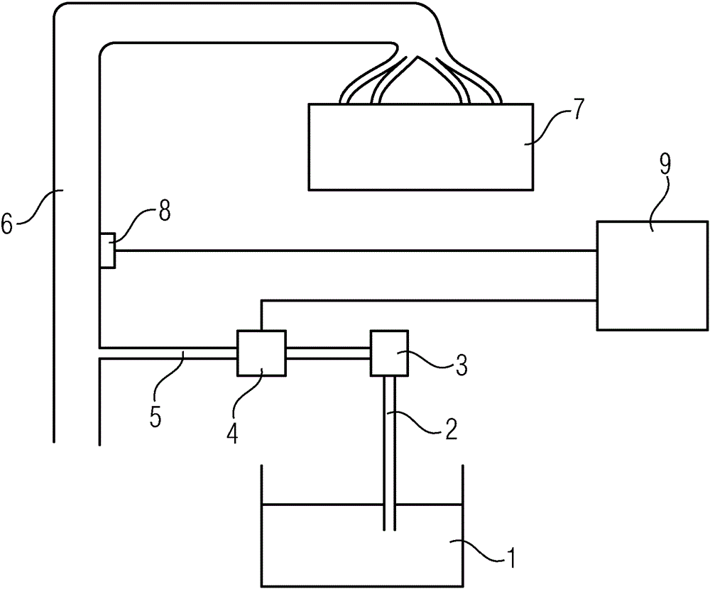
[0033] figure 1 A fuel tank ventilation system of a motor vehicle is schematically shown. The motor vehicle has an engine 7 , the combustion air of which is supplied via an intake duct 6 . Other components of the engine (injection system, etc.) are not illustrated here. The vehicle further has a fuel tank 1 from which fuel vapors are supplied via a line 2 to an activated carbon filter 3 and adsorbed by said activated carbon filter 3 . These hydrocarbons adsorbed in the filter are introduced via line 5 into the intake duct 6 of the engine 7 by opening the tank vent valve 4 and flushing at certain intervals to be supplied with the combustion air to the combustion process of the engine. A pressure sensor 8 is arranged in the region of the intake manifold 6 , wherein the pressure prevailing in the intake manifold can be measured by means of the pressure sensor 8 .

[0034] The system further has a control device 9 which can be part of the engine controller. The control device ...


PUM


Abstract

The invention relates to a method for operating a switch valve (4) which opens and closes a fluid line (5). The switch valve (4) is actuated by means of a pulse width modulated (PWM) signal. The switch valve (4) is actuated outside of the active operating time of the switch valve using PWM signals with an increasing or decreasing duty cycle. The duty cycle in which the switch valve (4) is opened is determined, and the duty cycle corresponding to the opening time is then used to actuate the switch valve (4) in order to open and close the switch valve during the active operating time of same. In this manner, the switch valve (4) can be actuated in a particularly precise manner.

Description

technical field [0001] The invention relates to a method for operating a switching valve that opens and closes a fluid line and is actuated by means of a pulse width modulated (PWM) signal to open and close a control device. [0002] Switching valves of this type are distinguished by a particularly simple design, since they are only moved by controlling between two switching states, in particular fully open or fully closed. Therefore, the switching valve does not assume any intermediate positions. Background technique [0003] The switching valve is actuated by means of a pulse width modulated (PWM) signal. This signal is defined by the control device based on various set point values ​​for the corresponding operating parameters. However, there is a risk in the event that the corresponding actual value deviates from the setpoint value, for example due to component tolerances, operating tolerances, etc., leading to an incorrect determination of the switching valve Open tim...

Claims


Application Information

Patent Timeline
Patent Type & Authority Applications(China)
IPC IPC(8): F02D41/00F02D41/24
CPCF02M25/0836F02M25/089F02D41/004F02D2041/2017F02D2041/2055F02D41/2464F02D2200/0406B60K15/03519B60K2015/0321B60K2015/03236B60K2015/03256B60K2015/03542B60K2015/03585F16K24/04G05B15/02G05D7/0635
Inventor R.豪弗勒
Owner VTESCO TECH GMBH
Why Eureka
Try Eureka