Electrically controlled hydrogen-spraying pressure regulating device of fuel cell system

A fuel cell system, fuel cell stack technology, applied in the direction of fuel cells, fuel cell additives, circuits, etc., can solve the problems of narrow working range of ejectors, inapplicability to automotive applications, high cost of hydrogen circulation pumps, etc., to achieve operational Effects of increased range, improved utilization, and wide operating range

Inactive Publication Date: 2015-12-23
TONGJI UNIV
View PDF4 Cites 22 Cited by
  • Summary
  • Abstract
  • Description
  • Claims
  • Application Information

AI Technical Summary

Problems solved by technology

However, the cost of the hydrogen circulation pump is high, the reliability is low, and the power consumption is large
2) Ejectors are used, although the ejectors are VENTURI effect operated, since they do not contain any moving parts and do not consume any power themselves, they have a simpler structure than electric drive hydrogen return pumps and they do not require any lubricant and Parasitic power consumption, and the disadvantage of using ejectors is that they have a narrow operating range and are not suitable for automotive applications. When idling, the hydrogen consumption flow may be lower than the minimum value that can produce the VENTURI effect
3) A hydrogen circulation pump is used in parallel with the ejector. Although this solution can use a smaller power hydrogen circulation pump to solve the problem of the narrow working range of the ejector, it has disadvantages in terms of cost, reliability and parasitic power consumption. Disadvantages cannot be avoided

Method used


Image

  • Electrically controlled hydrogen-spraying pressure regulating device of fuel cell system

Examples


Embodiment

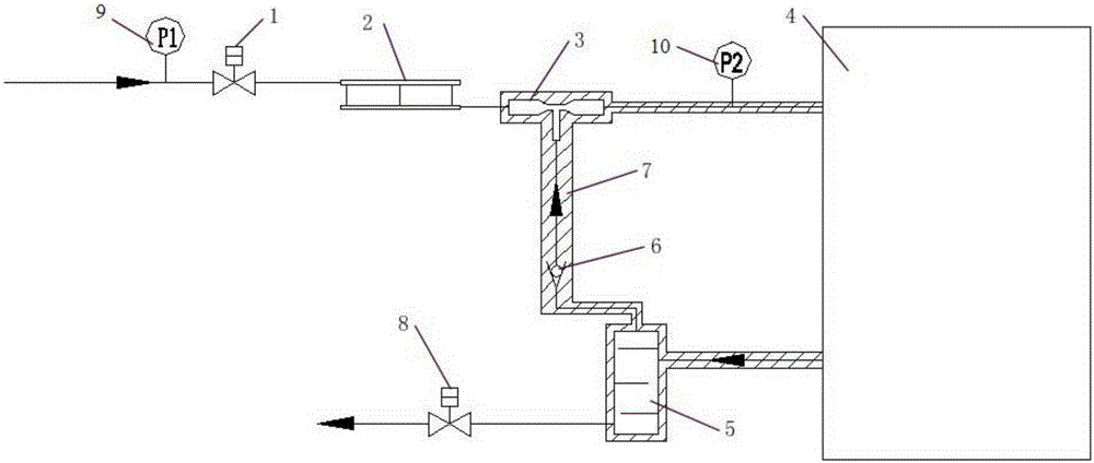
[0030] Such as figure 1 As shown, an electronically controlled hydrogen injection pressure adjustment device for a fuel cell system is used to control the intake air on the hydrogen side of the fuel cell system. The electronically controlled hydrogen injection pressure adjustment device includes:

[0031] Fuel cell stack 4: used for hydrogen fuel cell reaction to generate electricity;

[0032] Hydrogen side intake pressure control component: connected to the hydrogen intake pipe of the fuel cell stack to control the intake pressure of hydrogen and the return flow of hydrogen;

[0033] Drainage assembly: connected to the hydrogen exhaust pipe of the fuel cell stack to discharge the waste water;

[0034] Controller: respectively connected with the hydrogen side intake pressure control component and the hydrogen exhaust component, to control the hydrogen side intake pressure control component and the hydrogen exhaust component, and adjust the hydrogen gas intake side pressure. ...


PUM


Abstract

The invention relates to an electrically controlled hydrogen-spraying pressure regulating device of a fuel cell system, which is used for controlling air inflow at the hydrogen side of the fuel cell system. The electrically controlled hydrogen-spraying pressure regulating device comprises a fuel cell stack which is used for performing reaction of a hydrogen fuel cell to generate electric energy; a hydrogen side inlet pressure control component which is connected with a hydrogen inlet pipe of the fuel cell stack and is used for controlling an inlet pressure of the hydrogen and backflow of the hydrogen; a draining component which is connected with a hydrogen drain pipe of the fuel cell pack and is used for draining wastewater; and a controller which is respectively connected with the hydrogen side inlet pressure control component and the hydrogen draining component and is used for controlling the hydrogen side inlet pressure control component and the hydrogen draining component and regulating the hydrogen inlet side pressure. In comparison with the prior art, the electrically controlled hydrogen-spraying pressure regulating device of the fuel cell system has the advantages of improving the working environment of the fuel cell, being safe and reliable, being capable of preventing backflow, keeping the temperature of the returned hydrogen and the like.

Description

technical field [0001] The invention relates to the field of fuel cell systems, in particular to an electronically controlled hydrogen injection pressure regulating device for a fuel cell system. Background technique [0002] The fuel cell system used in the fuel cell hydrogen supply system is an electrochemical reaction device that feeds hydrogen and oxygen-containing air into the fuel cell stack as fuel gas and oxidant gas, and converts it into electrical power and water. A proton exchange membrane fuel cell (PEMFC) generally comprises 2 porous conductive electrode layers with a solid polymer electrolyte membrane disposed therebetween to form a membrane electrode assembly (MEA). To speed up the desired electrochemical reactions, both the anode and cathode electrodes contain catalysts. These catalysts are distributed on the surface of the membrane electrode layer. [0003] At the anode, hydrogen moves through the porous electrode layer and is oxidized by the catalyst to ...

Claims


Application Information

Patent Timeline
IPC IPC(8): H01M8/04
CPCH01M8/04H01M8/04082H01M8/04089Y02E60/50
Inventor 许思传沈春娟陈凤祥倪淮生
Owner TONGJI UNIV
Why Eureka
Try Eureka