Scanner for ultrasonic scanning detection and locking-adjusting method thereof
A technology of ultrasonic scanning and scanner, which is applied in the direction of material analysis, instruments, and measuring devices using sound waves/ultrasonic waves/infrasonic waves. The effect of convenient adjustment process
- Summary
- Abstract
- Description
- Claims
- Application Information
AI Technical Summary
Problems solved by technology
Method used
Image
Examples
Embodiment 1
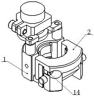
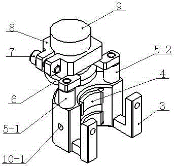
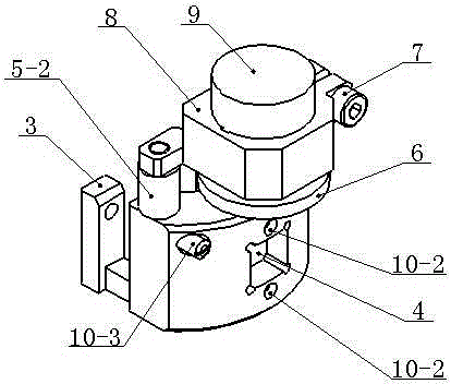
[0043] like figure 1 , figure 2 , image 3As shown, the scanner for ultrasonic scanning detection includes a left lock ring unit 1 and a right lock ring unit 2 connected with the left lock ring unit 1, and the left lock ring unit 1 includes a left outer lock ring 3 and a fitting The left inner lock ring 4 on the left outer lock ring 3 inwall, the left inner lock ring 4 can carry out the linear movement of the vertical direction with respect to the left outer lock ring 3, and the left outer lock ring 3 is provided with a vertical bar parallel to each other 5-1 and pole two 5-2, the bottom end of pole one 5-1 and the bottom end of pole two 5-2 are all fixed with left outer lock ring 3, the top of pole one 5-1 and pole The top of the two 5-2 is connected with the encoder swing seat 8 at the same time, the encoder swing seat 8 is provided with the encoder 9 and the fastening screw 7, the bottom end of the encoder 9 is provided with the encoder runner 6, and the encoder rotates ...
Embodiment 2
[0045] like Figure 4 , Figure 5 , Image 6 , Figure 7 , Figure 8 , Figure 9 , Figure 10 , Figure 11 , Figure 12 , Figure 13 , Figure 14 , Figure 15 , Figure 16 As shown, the left inner lock ring 4 is provided with a boss 4-1, and the boss 4-1 can move linearly in the centripetal direction relative to the stepped inner cavity 3-6 in the left outer lock ring 3, and the left outer lock ring 3 is provided with two threaded holes 3-4, and the stepped inner cavity 3-6 is arranged between the threaded holes 3-4, and the threaded holes 3-4 are provided with a plunger 10-2, and the plunger 1 10-2 Push the left inner lock ring backing surface 4-2 on the left inner lock ring 4 as a drive for linear movement of the boss 4-1 relative to the stepped inner cavity 3-6 in the left outer lock ring 3 in the centripetal direction force, the left outer lock ring 3 is provided with threaded hole 2 3-3, the threaded hole 2 3-3 is provided with plunger 2 10-1, the encoder swin...
Embodiment 3
[0047] The locking adjustment method of the scanner used for ultrasonic scanning detection: select the suitable scanner type for the outer wall 15 diameter of the small-diameter tube to be detected as required; align the inner cylindrical surface 4-4 of the left inner locking ring in the left locking ring unit with the Fit the outer wall 15 of the small-diameter tube, and keep this state; fit the inner cylindrical surface 12-3 of the probe wedge in the right locking ring unit to the outer wall of the small-diameter tube, and be in an up-down position with the left locking ring unit; make the right locking ring unit The right outer lock ring surface 2 11-5 of the probe wedge corresponds to the left outer lock ring surface 3-7 in the left lock ring unit; hold the right lock ring unit and push the left lock ring unit until it is close; pass The inner cavity of the right outer lock ring in the right lock ring unit 2 penetrates the locking screw 14, and is screwed in through two thr...
PUM
 Abstract
Description
Claims
Application Information
 - R&D
- Intellectual Property
- Life Sciences
- Materials
- Tech Scout
- Unparalleled Data Quality
- Higher Quality Content
- 60% Fewer Hallucinations
Browse by: Latest US Patents, China's latest patents, Technical Efficacy Thesaurus, Application Domain, Technology Topic, Popular Technical Reports.
© 2025 PatSnap. All rights reserved.Legal|Privacy policy|Modern Slavery Act Transparency Statement|Sitemap|About US| Contact US: help@patsnap.com


