Automatic loading machine and process thereof

An automatic and technological technology, applied in the direction of conveyor objects, transportation and packaging, etc., can solve problems such as large deviation, mechanism wear, and inaccurate equipment operation, and achieve the effect of high precision, overcoming easy wear, and precise operation

Inactive Publication Date: 2015-12-23
福建三锋机械科技有限公司
View PDF5 Cites 0 Cited by
  • Summary
  • Abstract
  • Description
  • Claims
  • Application Information

AI Technical Summary

Problems solved by technology

[0002] On the glass production line, the loading machine is an important equipment. Most of the vacuum suction cup devices in the existing loading machine use cam linkage mechanism or hydraulic cylinder to turn over. The wear and tear of the mechanism will soon lead to inaccurate operation of the entire equipment, and the deviation will become larger and larger

Method used


Image

  • Automatic loading machine and process thereof
  • Automatic loading machine and process thereof
  • Automatic loading machine and process thereof

Examples


Embodiment 1

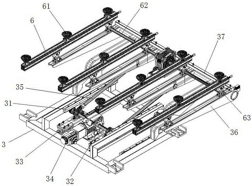
[0016] Embodiment one: if Figure 1~3 As shown, an automatic loading machine includes a frame 1, the bottom of the frame 1 is provided with a rail frame 2, and both sides of the rail frame 2 are provided with guide rails 21 that are guided along the front and rear, and on the rail frame 2 A base 3 that moves along the guide rail is provided, and a plurality of roller shafts 5 arranged along the left and right direction are evenly distributed on the upper part of the frame 1. The base 3 is provided with a slide rail 33 that is guided along the front and rear. 3 is provided with a base 4 that moves along the slide rail, and the base 4 is provided with a rotating shaft 32 that is driven by a motor 34 to rotate. The two sides of the base 3 are provided with racks 31 that are guided forward and backward. Both ends are provided with gears that engage with the rack 31, the two ends of the rotating shaft 32 are also hinged with connecting rods 35, the two sides of one end of the base ...


PUM


Abstract

The invention relates to an automatic loading machine and a process thereof. The automatic loading machine comprises a machine frame. A guiding rail frame is arranged at the bottom of the machine frame. Guiding rails guiding from front to back are arranged on the both sides of the guiding rail frame. A substrate moving along the guiding rails is arranged on the guiding rail frame. A plurality of roll shafts arranged in the left-right direction are evenly distributed on the upper portion of the machine frame. Sliding rails guiding from front to back are arranged on the substrate. A base moving along the sliding rails is arranged on the substrate. Rotary shafts driven by a motor to rotate are arranged on the base. Racks guiding from front to back are arranged on the two sides of the substrate. The two ends of the rotary shafts are all provided with gears engaged with the racks. The automatic loading machine is simple in structure, sturdy and durable.

Description

technical field [0001] The invention relates to an automatic chip loading machine and its technology. Background technique [0002] On the glass production line, the loading machine is an important equipment. Most of the vacuum suction cup devices in the existing loading machine use cam linkage mechanism or hydraulic cylinder to turn over. The wear and tear of the mechanism will soon lead to inaccurate operation of the whole equipment, and the deviation will become larger and larger. Contents of the invention [0003] The present invention makes improvements to the problems existing in the above-mentioned prior art, that is, the technical problem to be solved by the present invention is to provide an automatic chip loading machine and its technology, which are compact in structure, strong and durable. [0004] In order to solve the above technical problems, a technical solution of the present invention is: an automatic chip loading machine, including a frame, a guide rail...

Claims


Application Information

Patent Timeline
Patent Type & Authority Applications(China)
IPC IPC(8): B65G47/91
Inventor 谢煌明黄家富朱兴亮谢发斌
Owner 福建三锋机械科技有限公司
Why Eureka
Try Eureka