
Efficient oxygen increasing tank

An oxygen tank and high-efficiency technology, applied in the field of sewage treatment, can solve the problems of affecting the survival rate of aquarium fish, consuming the physical energy of aquarium fish, and gas source escaping the water surface, etc., achieving good oxygenation effect, preventing oxygen backflow, improving The effect of the degree of turbulence

Active Publication Date: 2015-12-23
HUAZHONG AGRI UNIV
View PDF6 Cites 7 Cited by
  • Summary
  • Abstract
  • Description
  • Claims
  • Application Information

AI Technical Summary

Problems solved by technology

[0002] In the prior art, most of the dissolved oxygen and oxygen-increasing devices in aquarium breeding and transportation equipment are sprayed at the water layer interface or convectively stirred in deep and shallow water layers, which requires a lot of power, and the potential energy of the water flow has a strong impact on the aquarium fish. Impact, even if the aquarium fish is injured by the impact, it also consumes the physical energy of the aquarium fish, which seriously affects the survival rate of the aquarium fish. Therefore, people improve this, such as "a high-efficiency Dissolved oxygen aerator", which includes a recovery oxygen chamber, the body of the high-efficiency pure oxygen dissolved oxygen aerator is a recovery oxygen chamber, the water inlet pipe of the recovery oxygen chamber is connected to the dissolved oxygen mixer, and the dissolved oxygen mixer is connected to the compressor through the air pipe The water and oxygen are mixed through the dissolved oxygen mixer and enter the oxygen recovery chamber through the water inlet pipe. The oxygen in the undissolved water escapes from the upper space of the oxygen recovery chamber, and the external pure oxygen escapes through the air inlet pipe and the oxygen recovery chamber. The oxygen is mixed at the top of the oxygen recovery chamber, and the mixed oxygen is pumped into the compressor through the suction pipe for compression, and the mixed compressed oxygen is added to the dissolved oxygen mixer through the air pipe for the use of dissolved oxygen and aeration
This patent uses oxygen into water to dissolve oxygen, and solves the problem of residual oxygen recovery and utilization, but the gas source used is still an extensive single-point injection, and the low pressure of the gas source makes the dissolved oxygen water limited to local limited waters. If the source pressure is high, the gas source will escape from the water surface, and the effect of dissolved oxygen is limited

Method used


Image

  • Efficient oxygen increasing tank
  • Efficient oxygen increasing tank
  • Efficient oxygen increasing tank

Examples


Embodiment 1

[0036] Embodiment 1: the impact of different oxygenation methods on dissolved oxygen:

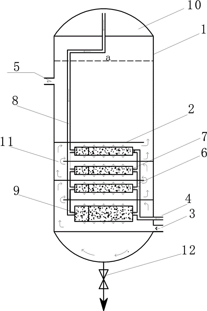
[0037] Parameter control: water flow is 600m 3 / h, the oxygen flow rate is 0.5m 3 / h, the cooling medium (cooling water) flow rate is 500m 3 / h, the temperature is 5°C, and the residual oxygen recovery chamber 10 (ie the pressure reflected by the top pressure gauge) is 0.12Mpa.

[0038] After testing, the dissolved oxygen content was 9.2mg / mL.

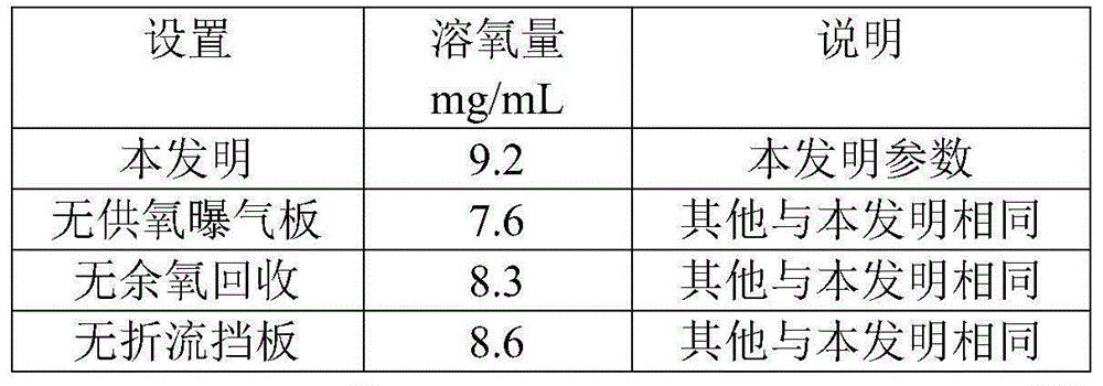
[0039] After testing, the influence of different oxygenation methods on dissolved oxygen is shown in Table 1. From Table 1, it can be seen that under the same conditions, the method according to the present invention has no oxygen supply aeration plate, no residual oxygen recovery device, and no baffle plate. , the amount of dissolved oxygen is large.

[0040] Table 1 Effect of different oxygenation methods on dissolved oxygen

[0041]

Embodiment 2

[0042] Embodiment 2: the influence of oxygen intake on dissolved oxygen:

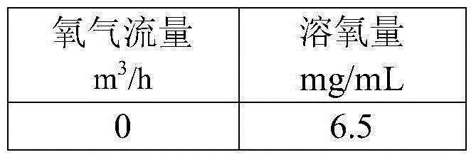
[0043] The structural parameters are the same as those in Example 1, except that the flow rate of oxygen intake is different. After testing, the influence of oxygen intake on dissolved oxygen is shown in Table 2. It can be seen from Table 2 that under the same conditions, the greater the oxygen intake, the greater the dissolved oxygen.

[0044] Table 2 The effect of oxygen intake on dissolved oxygen

[0045]

[0046]

Embodiment 3

[0047] Embodiment 3: the influence of temperature on dissolved oxygen:

[0048] The structural parameters are the same as in Example 1, only the temperature (regulated by the flow rate of the cooling medium) is different. After testing, the influence of temperature on dissolved oxygen is shown in Table 3, as can be seen from Table 3: under the same conditions, the lower the temperature, the higher the dissolved oxygen amount. big.

[0049] Table 3 Effect of temperature on dissolved oxygen

[0050]


PUM


Abstract

An efficient oxygen increasing tank comprises a tank body, an oxygen supply device and a residual oxygen recovery device are arranged in the tank body, baffling baffles are installed on the inner wall of the tank body, and the tank body is provided with a water supply opening, an oxygen supply opening and a water outlet. The oxygen supply device comprises an oxygen supply pipeline and an oxygen supply aeration plate, the oxygen supply opening is connected with the oxygen supply aeration plate through the oxygen supply pipeline, and the oxygen supply aeration plate is provided with a first micropore channel. The residual oxygen recovery device comprises a residual oxygen recovery pipeline and a residual oxygen aeration plate, the recovery end of the residual oxygen recovery pipeline is arranged on the top of the tank body, the release end of the residual oxygen recovery pipeline extends downwards and is connected with the residual oxygen aeration plate, and the residual oxygen aeration plate is provided with a second micropore channel. According to the efficient oxygen increasing tank, the closed tank body is adopted, oxygen is increased circularly, and the oxygen dissolving rate is increased; the baffling baffles are distributed in a staggered mode, so that the oxygen dissolving path of water flow in an oxygen dissolving layer is prolonged to the largest extent; by means of micropore aeration, gas is crushed into micro particles, and the oxygen dissolving rate is increased. The oxygen increasing efficiency is high, oxygen waste is little, and the efficient oxygen increasing tank can be used in high-density live fish transport and breeding.

Description

technical field [0001] The invention belongs to the field of sewage treatment and relates to an aeration device, in particular to a high-efficiency aeration tank. Background technique [0002] In the prior art, most of the dissolved oxygen and aeration devices in aquarium breeding and transportation equipment are sprayed at the interface of the water layer or convectively stirred in the deep and shallow water layers, which requires a lot of power, and the potential energy of the water flow has a strong impact on the aquarium fish. Impact, even if the aquarium fish is injured by the impact, it also consumes the physical energy of the aquarium fish, which seriously affects the survival rate of the aquarium fish. Therefore, people improve this, such as the Chinese patent No. ZL: 2009100085704 "A High Efficiency Dissolved oxygen aerator", which includes a recovery oxygen chamber, the body of the high-efficiency pure oxygen dissolved oxygen aerator is a recovery oxygen chamber, t...

Claims


Application Information

Patent Timeline
IPC IPC(8): A01K63/04
CPCA01K63/042
Inventor 黄汉英熊善柏赵思明胡月来马章宇
Owner HUAZHONG AGRI UNIV
Learn More