
electric assist bike

An electric assist, bicycle technology, applied in vehicle components, rider drive, transportation and packaging, etc., can solve the problems of reduced torque detection ability, inability to transmit pedal rotation, low detection ability, etc., to improve reliability and ease of use. And reliable detection, rapid detection effect

Active Publication Date: 2017-10-20
PANASONIC INTELLECTUAL PROPERTY MANAGEMENT CO LTD
View PDF3 Cites 0 Cited by
  • Summary
  • Abstract
  • Description
  • Claims
  • Application Information

AI Technical Summary

Problems solved by technology

Therefore, the vibration during the switching operation of these one-way clutches 206, 252, 258 or the vibration during the meshing operation of the cam portion and the overriding operation are directly transmitted to the human force transmission body 203 provided with the torque sensor 209 or the resultant force of the torque sensor 260. body 255, therefore, it becomes noise during torque detection, and the torque detection capability may decrease
[0024] In addition, in order to maintain a good assembled state after the one-way clutches 206, 252, 258 are installed on the human power transmission body 203 or the combined force body 255, it is preferable to use a material with excellent wear resistance as the human power transmission body 203 or the combined force body 255, or Carry out heat treatment, but must form the magnetostrictive generation part of torque sensor 209,260 on the surface of manpower transmission body 203 or resultant force body 255, therefore, the material of manpower transmission body 203 or resultant force body 255 is extremely limited, depending on the situation, Sometimes have to use materials with low detection ability of torque
[0025] In addition, since the one-way clutches 206, 252, and 258 are installed on the human power transmission body 203 or the combined force body 255, even if the reverse wheel brake is to be provided on the hub of the rear wheel, the pedal is rotated in the opposite direction to that of the forward running. , the rotation of the pedals cannot be transmitted to the drive sprockets 102, 201, 257 or the chains 105, 208, 256, and cannot correspond to

Method used


Image

  • electric assist bike
  • electric assist bike
  • electric assist bike

Examples


Embodiment Construction

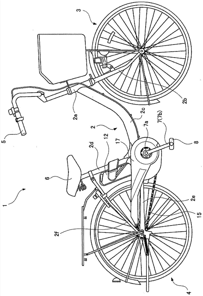
[0068] Hereinafter, a motor-assisted bicycle according to an embodiment of the present invention will be described based on the drawings. In addition, the left-right direction and the front-rear direction in the following description refer to directions in a state where the electrically assisted bicycle 1 is mounted facing the traveling direction, but the configuration of the present invention is not limited to the directions described below.

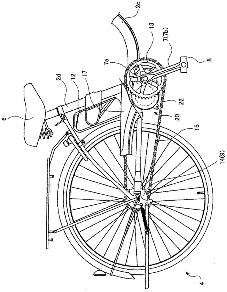
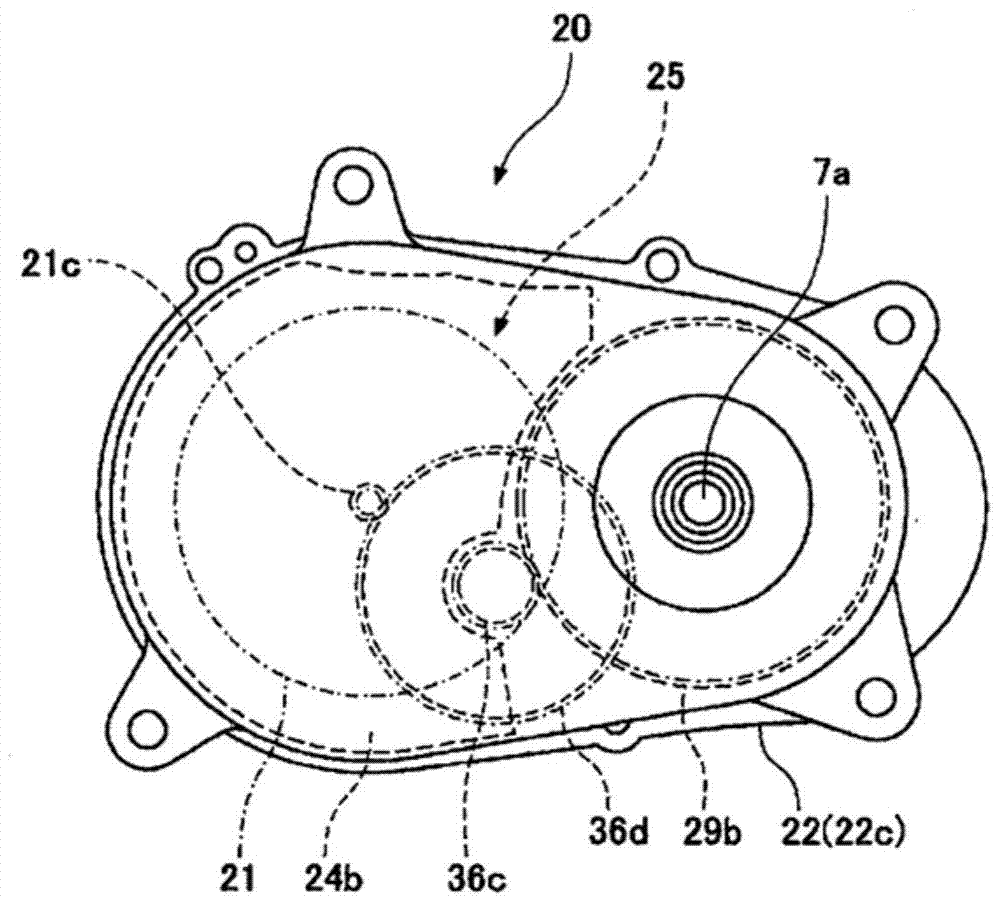
[0069] figure 1 , figure 2 1 in it is the motor-assisted bicycle according to the embodiment of the present invention. Such as figure 1 , figure 2 As shown, this power-assisted bicycle 1 includes: a metal frame 2 composed of a head pipe 2a, a front fork 2b, a main pipe 2c, a seat pipe 2d, a chain bracket 2e, a seat bracket 2f, etc.; The front wheel 3 at the lower end; the rear wheel 4 rotatably attached to the rear end of the chain bracket 2e; the handlebar 5 for changing the direction of the front wheel; the seat 6; An electri...


PUM


Abstract

The present invention provides an electric-assisted bicycle equipped with a so-called single-shaft motor drive unit that can maintain a good torque detection capability. Arranged on the outer periphery of the crankshaft (7a) is a cylindrical human power transmission body (28) forming a torque sensor (31) for detecting human power driving force, which transmits the human power driving force and the auxiliary driving force from the electric motor (21). The resultant force body (29). There is no one-way clutch in the transmission path of the driving force through the crankshaft (7a), the human power transmission body (28) and the resultant force body (28). As the crankshaft (7a) rotates, the human power transmission body (28) and the resultant force body (28) The resultant body (29) also usually rotates. In addition, a rotation detector (10) for detecting the rotation of the resultant force body (29) is provided.

Description

technical field [0001] The present invention relates to a motor-assisted bicycle that can be driven by a human driving force realized by pedaling force and an auxiliary driving force generated by an electric motor. Background technique [0002] There is known a motor-assisted bicycle that has a motor powered from an accumulator such as a storage battery, detects a human-powered driving force composed of a pedaling force applied to the pedals with a torque sensor, etc., and adds a motor that corresponds to the human-powered driving force. The auxiliary driving force (assist force) can easily drive even when going uphill. [0003] In this electrically assisted bicycle, there is a structure in which a motor drive unit incorporating a motor and the like is arranged at a portion where a crankshaft is provided. In the power-assisted bicycle with such an arrangement structure, the relatively heavy motor drive unit is arranged at a lower position in the center (that is, between the...

Claims


Application Information

Patent Timeline
Patent Type & Authority Patents(China)
IPC IPC(8): B62M6/55B62M6/50
CPCB62M6/50B62M6/55
Inventor 川上将史小泽聪藤井直起
Owner PANASONIC INTELLECTUAL PROPERTY MANAGEMENT CO LTD
Learn More