
Nesting process machining method for off-axis reflection type optical part

A technology for optical parts and process processing, which is applied in the processing field of off-axis reflective optical parts, can solve problems such as impact, measurement error increase, manual repair high-frequency residual error, etc., and achieves wide adaptability, simple structure, and adaptability strong effect

Active Publication Date: 2015-12-16
NANJING ZHONGKE ASTROMOMICAL INSTR
View PDF5 Cites 3 Cited by
  • Summary
  • Abstract
  • Description
  • Claims
  • Application Information

AI Technical Summary

Problems solved by technology

[0002] The off-axis quantity of off-axis optical parts is a "virtual quantity" in the process of processing (in the form of figure 1 Take the off-axis paraboloid aberration-free point detection optical path as an example), because the off-axis part does not have a center point that actually exists, so it must be measured by some auxiliary quantities, such as figure 1 The off-axis amount d is obtained after fitting the two lengths of L1 and L2. When the lengths of L1 and L2 are longer, the measurement error of L1 and L2 will increase, which directly leads to the off-axis amount d and eccentricity e. 2 The error will also become larger, and at the same time, because there is no substantial center point of the optical axis, the difficulty of controlling the focal length will also increase
[0003] In addition, since the off-axis optical part itself is not a "rotationally symmetrical" shape structure, only the single-mirror manual repair process can be used. This process will inevitably produce manual high-frequency residual errors. This residual error requires high optical uniformity. High system will affect

Method used


Image

  • Nesting process machining method for off-axis reflection type optical part
  • Nesting process machining method for off-axis reflection type optical part
  • Nesting process machining method for off-axis reflection type optical part

Examples


Embodiment Construction

[0028] The present invention will be described in further detail below in conjunction with the accompanying drawings.

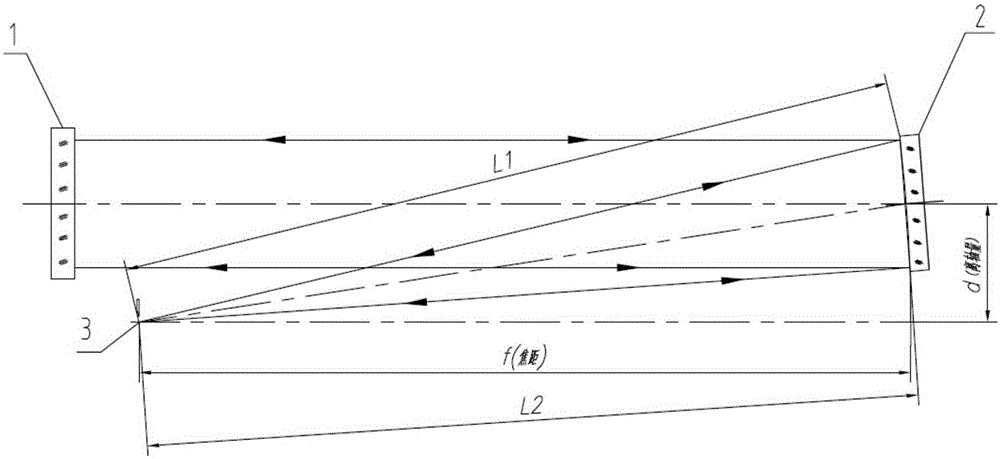
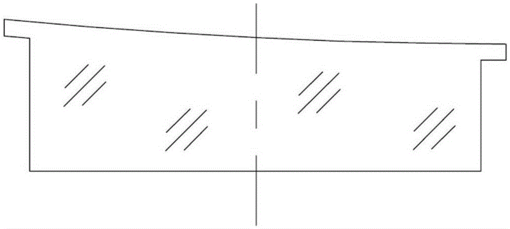
[0029] figure 2 and image 3 It is an example of a special-shaped off-axis mirror structure as a processing object of an off-axis reflective optical part nesting process processing method of the present invention.

[0030] The specific steps of an off-axis reflective optical part nesting process processing method of the present invention are as follows:

[0031] 1. Measure the shape of off-axis aspheric optical parts, and leave a processing allowance for subsequent processes according to the processing technology;

[0032] 2. According to the measurement results of step 1, design and grind the nested master mirror. The so-called master mirror is the non-off-axis part of the off-axis mirror that is "completed", that is, it can be combined with the off-axis part to form a complete rotationally symmetrical area , the splicing gap between the mother mirror an...


PUM


Abstract

The invention discloses a nesting process machining method for an off-axis reflection type optical part. The nesting process machining method includes the steps that the outline of an off-axis aspheric surface optical part is measured, and the machining allowance for the subsequence procedure is reserved according to the machining process; a nesting mother lens is designed and ground; an abrasive disk of an assembly is designed and machined; the machined abrasive disk is fed in an inverted covering mode, and the off-axis aspheric surface optical part is put in the nesting mother lens; an opposite abutting mechanism is embedded to control the splicing gap between the nesting mother lens and the off-axis aspheric surface optical part; heated sealing wax is poured in, and a back plate is arranged in a cushioning mode; and finally a bottom plate of the assembly is bonded, is overturned and stands so that glue can be solidified. A common machine tool is used, the off-axis amount can be controlled to be within the range of + / - 0.1 mm, requirements for equipment are lowered, and the machining efficiency and the smoothness degree of a lens surface are improved. As a tool can be reused, the nesting process machining method can be reused as well.

Description

technical field [0001] The invention belongs to the field of optical processing, and in particular relates to a processing method for an off-axis reflective optical part. Background technique [0002] The off-axis quantity of off-axis optical parts is a "virtual quantity" in the process of processing (in the form of figure 1 Take the off-axis paraboloid aberration-free point detection optical path as an example), because the off-axis part does not have a center point that actually exists, so it must be measured by some auxiliary quantities, such as figure 1 The off-axis amount d is obtained after fitting the two lengths of L1 and L2. When the lengths of L1 and L2 are longer, the measurement error of L1 and L2 will increase, which directly leads to the off-axis amount d and eccentricity e. 2 The error will also become larger, and at the same time, because there is no substantial center point of the optical axis, the difficulty of controlling the focal length will also increa...

Claims


Application Information

Patent Timeline
IPC IPC(8): B24B13/00
CPCB24B13/00
Inventor 李季
Owner NANJING ZHONGKE ASTROMOMICAL INSTR
Learn More