
Incremental rate distortion optimization method based on free viewpoint video depth map coding

A technology of depth map coding and rate-distortion optimization, which is applied in the field of video coding, can solve problems such as large amount of calculation, inability to guarantee the quality of synthetic view as a whole, unfavorable real-time system applications, etc., and achieve the effect of reducing computational complexity

Active Publication Date: 2015-12-09
西安迪威码半导体有限公司
View PDF4 Cites 1 Cited by
  • Summary
  • Abstract
  • Description
  • Claims
  • Application Information

AI Technical Summary

Problems solved by technology

The first method used for distortion prediction of depth sequence coding is the traditional distortion calculation method, such as SSD (SumofSquaredDifference) and SAD (SumofAboluteDifferences), which has low computational complexity and is easy to implement in hardware, but cannot guarantee the quality of synthetic views as a whole.
Nowadays, the depth sequence coding distortion prediction method is to first calculate the depth block distortion D through SSD depth , and then repeatedly execute the viewpoint synthesis algorithm, wherein six virtual viewpoints need to be synthesized when coding the middle coding viewpoint, three virtual viewpoints need to be synthesized when coding the left or right coding viewpoint, and the sum D of SVDC (Synthesized View Distortion Change) of all virtual viewpoints is calculated VSO , and finally get the depth patch distortion D depth and D VSO The weighted average value of is used as D in the rate-distortion cost. This method is very computationally intensive and is not conducive to the application of real-time systems.

Method used


Image

  • Incremental rate distortion optimization method based on free viewpoint video depth map coding
  • Incremental rate distortion optimization method based on free viewpoint video depth map coding
  • Incremental rate distortion optimization method based on free viewpoint video depth map coding

Examples


Embodiment Construction

[0023] Specific embodiments of the present invention will be described in detail below.

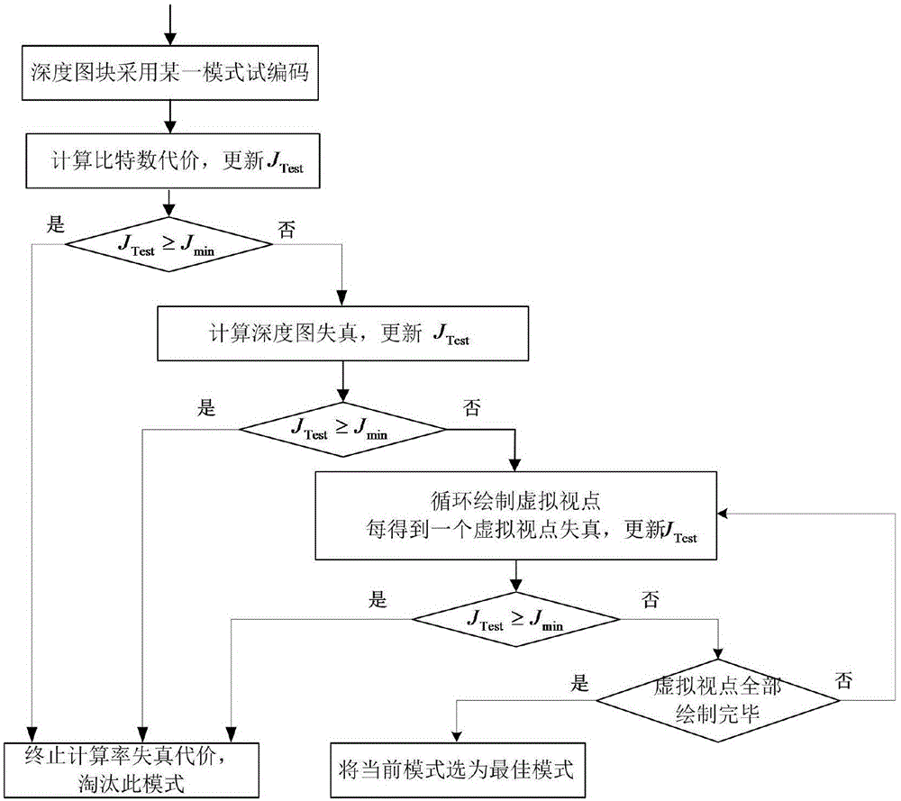
[0024] A progressive rate-distortion optimization method for free-viewpoint video depth map coding, comprising the steps of:

[0025] S1: During the encoding process of the depth map, sequentially traverse multiple encoding modes (try one encoding mode each time) to try encoding the depth image block;

[0026] S2: Predict the required number of bits R, and calculate the temporary rate-distortion cost J Test1 :

[0027] J Test1 =λR,

[0028] Where λ is the Lagrangian multiplier;

[0029] S3: The temporary rate-distortion cost J Test1 with the existing minimum rate-distortion cost J min for comparison, if J Test1 ≥J min , then the rate-distortion cost calculation of this mode is terminated, and this mode is eliminated; otherwise, the depth block distortion D of this mode is calculated depth ,

[0030] S4: Through the traditional distortion model SAD (SumofAbsoluteDifferences, the ...


PUM


Abstract

The invention relates to an incremental rate distortion optimization method based on free viewpoint video depth map coding. The incremental rate distortion optimization method comprises the following steps: (1), trying to code a depth map block by adopting a certain coding mode so as to obtain a bit number cost, eliminating the mode if the bit number cost is more than a minimal rate distortion cost Jmin, and or else, entering a step (2); (2), calculating distortion of the depth map block, summing the distortion and the bit number cost after weighing so as to obtain a temporary rate distortion cost, eliminating the mode if the temporary rate distortion cost is more than the Jmin, and or else, entering a step (3); (3), entering a synthetic virtual viewpoint cycle, summing distortion of one virtual viewpoint obtained every time and the original rate distribution cost after weighing, stopping calculation of the rate distortion cost in the mode if the sum is more than the Jmin, and or else, continuously calculating distortion of a next virtual viewpoint; and (4), eliminating the mode if the obtained distortion is more than Jmin after all virtual viewpoints are synthesized, and or else, selecting the mode as the optimal mode.

Description

technical field [0001] The invention relates to the field of video coding, in particular to a progressive rate-distortion optimization method for free-viewpoint video depth map coding. Background technique [0002] 3D video can make people experience the video scene more immersively and greatly enhance the user's visual experience. It is one of the development hotspots in the video field at present when it is applied to various industries such as 3D TV and virtual viewpoint synthesis. The International Moving Picture Experts Group MPEG (Moving Picture Experts Group) and Video Video Coding Experts Group VCEG (Video Coding Experts Group) established the Video Coding Joint Working Group JCT-VC (The Joint Collaborative Team Video Coding) to formulate the high-efficiency video coding standard HEVC (High Efficiency Video Coding). As a promotion of HEVC, 3D-HEVC is developed for 3D video coding. [0003] In 3D-HEVC, multi-view video plus depth video is used as its data format, whe...

Claims


Application Information

Patent Timeline
IPC IPC(8): H04N19/147H04N19/597
Inventor 霍俊彦胡文麟莫冬春杨付正
Owner 西安迪威码半导体有限公司
Learn More