
Circularly polarized antenna

An electric dipole, ground plane technology, applied in the direction of antenna, antenna array, antenna grounding switch structure connection, etc., to achieve the effect of high gain, wide axial ratio bandwidth and simple structure

Active Publication Date: 2015-12-09
CITY UNIVERSITY OF HONG KONG
View PDF5 Cites 4 Cited by
  • Summary
  • Abstract
  • Description
  • Claims
  • Application Information

AI Technical Summary

Problems solved by technology

This will be affected by the antenna's ability to receive radio waves will be affected by its direction, that is, there will be polarization loss

Method used


Image

  • Circularly polarized antenna
  • Circularly polarized antenna
  • Circularly polarized antenna

Examples


Embodiment Construction

[0026] In the following description, numerous specific details are set forth to provide a thorough understanding of various embodiments of the present disclosure. Those skilled in the relevant art will recognize that the techniques described in this disclosure can be practiced without one or more of the specific details, or with other methods, components, materials, etc. In other instances, well-known structures, materials, or operations are not shown or described in detail in the present disclosure to avoid obscuring certain aspects.

[0027] "One embodiment" or "a certain embodiment" mentioned in this specification means that specific features, structures or characteristics related to this embodiment are included in at least one embodiment. Thus, appearances of phrases in this specification such as "in one embodiment," "in an aspect," or "in an embodiment" do not necessarily refer to the same embodiment. Furthermore, the particular feature, structure or characteristic may b...


PUM


Abstract

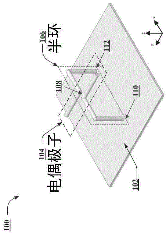
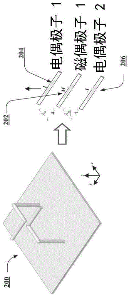
A circularly polarized antenna exhibiting a high performance characteristic can be produced by utilizing a ground plane, a half-loop, and an electric dipole in a predetermined configuration. The circularly polarized antenna can provide benefits, such as wide axial ratio bandwidth, high gain, and simple structure, over other unidirectional circularly polarized antennas.

Description

technical field [0001] The present disclosure relates to circularly polarized antennas used in numerous wireless applications, such as high performance circularly polarized antennas. Background technique [0002] An antenna is an electronic device that converts electrical current into radio waves, or vice versa. Antennas are commonly used with and as part of radio transmitters or receivers. Antennas are widely used in systems such as radio broadcasting, television, radar, cell phones and satellite communications. Antenna polarization refers to the direction of the far-field electric field vector generated by it, which depends on the physical structure of the antenna and the direction of the antenna. The orientation of the antenna is different from the directionality of the antenna. [0003] Antenna polarization is conventionally understood to mean the direction of the far-field electric field vector it is said to radiate. There are two types of antenna polarization, namel...

Claims


Application Information

Patent Timeline
Patent Type & Authority Applications(China)
IPC IPC(8): H01Q1/50
CPCH01Q21/245H01Q21/29
Inventor 薛泉廖绍伟吴鹏
Owner CITY UNIVERSITY OF HONG KONG
Learn More