
An embedded track structure suitable for medium and small span bridges and its construction method

An embedded track and construction method technology, applied in the field of rail transit, can solve problems such as high construction requirements, slow construction progress, and large dead load in the second phase of the bridge, and achieve good vibration and noise reduction effects, increase overall stability, and reduce Effect of Structural Requirements

Active Publication Date: 2017-03-22
CHENGDU XINZHU ROAD & BRIDGE MASCH CO LTD
View PDF6 Cites 1 Cited by
  • Summary
  • Abstract
  • Description
  • Claims
  • Application Information

AI Technical Summary

Problems solved by technology

[0003] The traditional ballasted track has a lot of maintenance and repairs, and it is easy to cause gravel splashes during the operation of the train, especially when it is running in the city, it is easy to cause safety accidents
However, the traditional ballastless track structure has disadvantages such as large self-weight and the second-stage dead load of the bridge, high structural requirements and engineering cost of the bridge, high construction requirements, and slow construction progress, which cannot meet the requirements of rapid construction in cities.
[0004] And whether it is a traditional ballast track or a traditional ballastless track, the fastener track is used, and its vibration and noise reduction effect is not good, and it cannot meet the requirements of environmental protection.

Method used


Image

  • An embedded track structure suitable for medium and small span bridges and its construction method
  • An embedded track structure suitable for medium and small span bridges and its construction method
  • An embedded track structure suitable for medium and small span bridges and its construction method

Examples


Embodiment 1

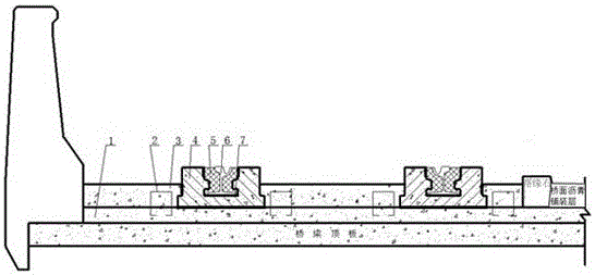
[0048] Such as figure 1 , 6 As shown, an embedded track structure suitable for medium and small-span bridges includes a bridge roof, a bridge deck cast-in-place layer 1, a connecting member 2, a reinforced concrete base 3, a bearing groove 4 and a grooved track 6, and the bridge deck is now The pouring layer 1 is poured on the bridge roof, and there are two grooved rails 6 and two rail bearing grooves 4, each of which is embedded in a rail bearing groove 4, and the two grooved rails The rail bearing grooves 4 are embedded in the reinforced concrete base 3 parallel to each other along the longitudinal direction, and the reinforced concrete base 3 is arranged on the cast-in-place layer 1 of the bridge deck and connects the cast-in-place layer 1 of the bridge deck with the reinforced concrete base 3 through the connecting member 2 into a whole.

[0049] Both sides of the lower part of the rail groove 4 protrude outward to form a "convex" structure.

[0050] The rail bearing gr...

Embodiment 2

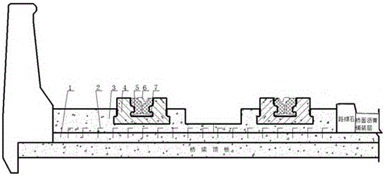
[0056] Such as figure 2 ,6 As shown, an embedded track structure suitable for medium and small-span bridges includes a bridge roof, a bridge deck cast-in-place layer 1, a connecting member 2, a reinforced concrete base 3, a bearing groove 4 and a grooved track 6, and the bridge deck is now The pouring layer 1 is poured on the bridge roof, and there are two grooved rails 6 and two rail bearing grooves 4, each of which is embedded in a rail bearing groove 4, and the two grooved rails The rail bearing grooves 4 are embedded in the reinforced concrete base 3 parallel to each other along the longitudinal direction, and the reinforced concrete base 3 is arranged on the cast-in-place layer 1 of the bridge deck and connects the cast-in-place layer 1 of the bridge deck with the reinforced concrete base 3 through the connecting member 2 into a whole.

[0057] Both sides of the lower part of the rail groove 4 protrude outward to form a "convex" structure.

[0058] The rail bearing gro...

Embodiment 3

[0064] Such as image 3 As shown, an embedded track structure suitable for medium and small-span bridges includes a bridge roof, a bridge deck cast-in-place layer 1, a connecting member 2, a reinforced concrete base 3, a bearing groove 4 and a grooved track 6, and the bridge deck is now The pouring layer 1 is poured on the bridge roof, and there are two grooved rails 6 and two rail bearing grooves 4, each of which is embedded in a rail bearing groove 4, and the two grooved rails The rail bearing grooves 4 are embedded in the reinforced concrete base 3 parallel to each other along the longitudinal direction, and the reinforced concrete base 3 is arranged on the cast-in-place layer 1 of the bridge deck and connects the cast-in-place layer 1 of the bridge deck with the reinforced concrete base 3 through the connecting member 2 into a whole.

[0065] The rail bearing groove 4 is a prefabricated concrete rail bearing groove.

[0066] The connecting member 2 is pre-embedded in bot...


PUM


Abstract

The invention discloses an embedded track structure suitable for a middle-span and small-span bridge. The embedded track structure comprises a bridge top plate, a bridge deck cast-in-place layer, a connecting element, a reinforced concrete base, two track bearing grooves and two groove type tracks, wherein the bridge deck cast-in-place layer is cast on the bridge top plate; each groove type track is arranged in the corresponding track bearing groove in an embedded manner; the two track bearing grooves are embedded into the reinforced concrete base in parallel in the longitudinal direction; the reinforced concrete base is arranged on the bridge deck cast-in-place layer; the bridge deck cast-in-place layer and the reinforced concrete base are connected into a whole through the connecting element. The embedded track structure has the benefits as follows: by adopting the embedded track structure, the vibration reduction and noise reduction effects are good; the structure is simple, the self weight is light, structural requirements of a city bridge are reduced, the construction cost is reduced and city quick construction requirements are met; the connecting element adopts a rigid connection mode, so that the whole stability of the track structure on the bridge is improved.

Description

technical field [0001] The invention relates to a track structure, in particular to an embedded track structure suitable for small and medium-span bridges, and a construction method for the embedded track structure, which is suitable for medium and small-span bridges and belongs to the technical field of rail transportation. Background technique [0002] Modern tram lines generally run through urban areas or near residents. Therefore, the requirements for environmental protection are high, and noise and vibration need to be strictly controlled, which requires that the track structure should have good vibration and noise reduction performance. Moreover, since the construction of rail lines in cities has a great impact on urban traffic, it is necessary to make the track structure as simple as possible when designing the track, which is suitable for rapid construction and shortens the construction period. [0003] The traditional ballasted track has a lot of maintenance and re...

Claims


Application Information

Patent Timeline
Patent Type & Authority Patents(China)
IPC IPC(8): E01D19/12E01D21/00
Inventor 焦洪林罗炯杨刚杨强刘光胜
Owner CHENGDU XINZHU ROAD & BRIDGE MASCH CO LTD
Learn More