a tubular motor

A technology of tubular motor and manual mechanism, applied in the direction of electrical components, electromechanical devices, mechanical equipment, etc., can solve the problems of increasing the number of operators, laborious unlocking process, slowness, etc., and achieve the effect of labor-saving manufacturing cost and energy consumption reduction

Active Publication Date: 2017-11-21
NINGBO YORRTE MECHANIC & ELECTRONICS TECH
View PDF1 Cites 0 Cited by
  • Summary
  • Abstract
  • Description
  • Claims
  • Application Information

AI Technical Summary

Problems solved by technology

[0010] It takes 4 steps to complete the clutch process, and a large amount of power will be consumed in the transmission of torque in each step, so that the operator needs to spend a large amount of force on the manual mechanism 6. Although the original existing transmission mode is changed, the energy consumption is still high. It takes a lot of force to drive the load, especially in the technical solution of the application documents, the brake device 3 is set between the motor 1 and the reduction device 2, and the process of unlocking the brake device 3 needs to be driven by the rotor 11 of the motor 1 is quite laborious. And the slow unlocking process will undoubtedly increase the force required for the operator to manually operate

Method used


Image

  • a tubular motor
  • a tubular motor
  • a tubular motor

Examples


Embodiment 1

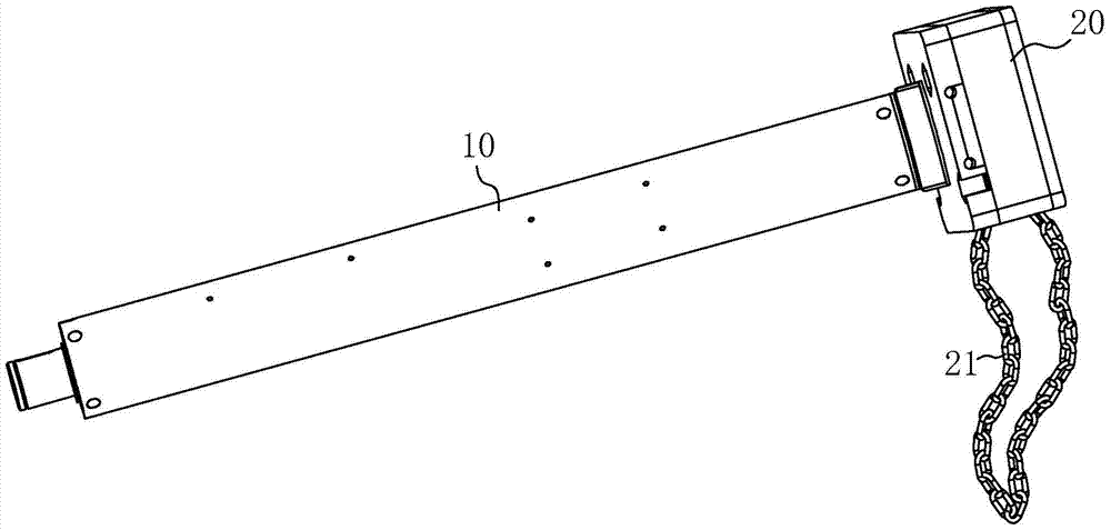
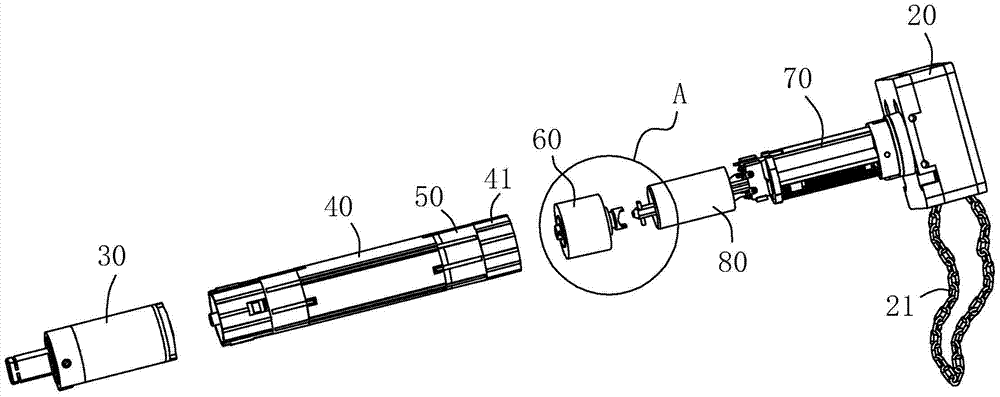
[0043] to combine figure 1 and figure 2 , a tubular motor includes a reduction device 30, a motor 40, a brake device 50, a clutch device, and a travel device 70 in sequence. The travel device 70 includes a manual mechanism 20 connected to one side, and the manual mechanism 20 includes internally arranged gears that wind around the gears. The chain 21 and the long shaft 71 rotating with the gear pull the chain 21 to drive the gear to rotate so as to drive the long shaft 71 to rotate. The long shaft 71 runs through the capacitor 80, and the capacitor 80 is connected with the travel device 70 to provide a starting current. The motor pipe 10 is sleeved on the outside and is fixed by screws and the reduction device 30, the clutch device and the stroke device. The motor pipe 10 in the present invention is fixed and does not rotate.

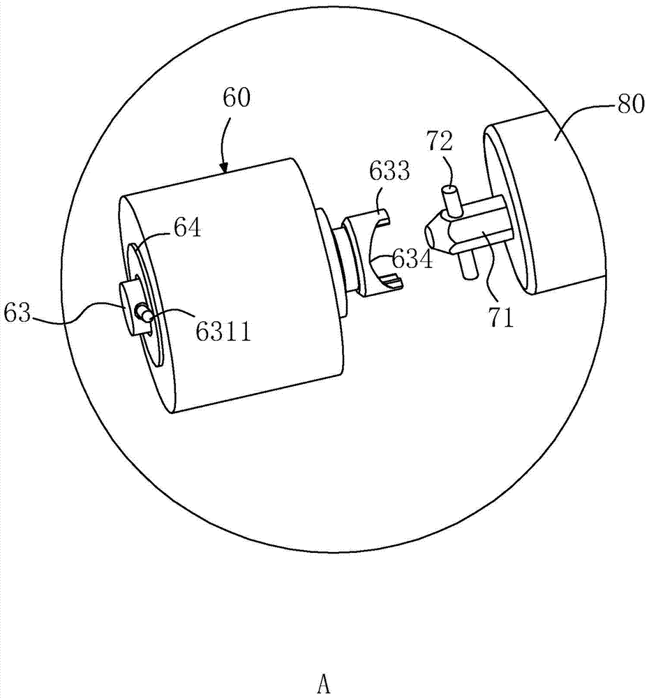
[0044] see Figure 3 to Figure 5 , the clutch device includes a lower clutch 60, the lower clutch 60 includes a clutch seat 61 and a clutch member 6...

Embodiment 2

[0053] The difference between Embodiment 1 lies in the operation mode of the manual mechanism 60. The gear in the manual mechanism 60 is changed to a worm gear transmission mode, and the worm is connected to a manual shaft to drive the worm gear to rotate, thereby driving the long axis 71 to rotate.

Embodiment 3

[0055] The difference between Embodiment 1 lies in the operation mode of the manual mechanism 60. The gear in the manual mechanism 60 is changed to a long-axis bevel gear, and the long-axis bevel gear is fixed to the long-axis 71, and a hand-shaft bevel gear is provided to mesh with the long-axis bevel gear. , The bevel gear of the hand shaft is driven to rotate by the hand shaft.


PUM


Abstract

The invention discloses a tubular motor. A brake device is arranged between the motor and a stroke device. A clutch mechanism is arranged between the brake device and the stroke device. The clutch mechanism includes an upper clutch fixed at one end of the rotor, and a lower clutch matched with the upper clutch. Clutch, the lower clutch includes a clutch part that is rotated by the long axis and can move axially. The lower clutch has a first elastic part that maintains a tendency to disengage from the upper clutch. One end of the rotor is inserted with a first elastic part that can collide with the clutch part. A driving part, the brake device includes a friction plate and a first brake plate close to the side of the friction plate, the first brake plate is radially arranged on the rotor and can drive the second drive part separated from the friction plate to connect with the rotor, the second The first driving part is in contact with the second driving part, and the brake device is arranged between the clutch mechanism and the motor, and the cooperation between the clutch part and the upper clutch is used to drive the rotor to rotate, reducing the energy consumption in the process of torque transmission, so that during manual operation It saves effort.

Description

technical field [0001] The invention relates to a tubular motor. Background technique [0002] Tubular motors are widely used in various electric lift doors and windows, sunshade systems, projection screens and other fields, including external motor tubes, motor assemblies, brake assemblies, deceleration assemblies, and travel control assemblies. Press the lift switch when the power is on Control the rotation of the motor assembly to drive the rotation of the motor tube through the deceleration output of the deceleration assembly, and the rotation of the motor tube and the rotation of the electric outer tube realize the lifting of doors, windows or projection screens. [0003] Usually, the tubular motor is also equipped with a manual operating mechanism. When the power is off, the motor assembly cannot work, and the electric operating mechanism needs to be used to drive the doors, windows or projection screens up and down. In the Chinese patent application number 2012103639...

Claims


Application Information

Patent Timeline
Patent Type & Authority Patents(China)
IPC IPC(8): H02K7/00H02K7/108F16D67/02
Inventor 魏春辉喻丹
Owner NINGBO YORRTE MECHANIC & ELECTRONICS TECH
Why Eureka
Try Eureka