
Multi-head minor-diameter long-spiral drilling machine and application thereof in construction of cast-in-situ major-diameter tubular pile

A technology of long auger drilling rig and large-diameter pipe, applied in the direction of drill pipe, drill pipe, casing, etc., can solve the problems of difficult construction of immersed pipe, significant soil squeeze effect, etc., and achieves clear construction process, good pile forming effect, low cost effect

Active Publication Date: 2015-12-02
HOHAI UNIV
View PDF5 Cites 5 Cited by
  • Summary
  • Abstract
  • Description
  • Claims
  • Application Information

AI Technical Summary

Problems solved by technology

[0004] Purpose of the invention: The purpose of the present invention is to overcome the above-mentioned defects, solve the technical problems such as the difficulty of immersed pipe construction and the significant soil squeezing effect when the wall thickness of the cast-in-place large-diameter pipe pile is large, and propose a multi-head small-diameter long auger and its Application in the construction of cast-in-place large-diameter pipe piles

Method used


Image

  • Multi-head minor-diameter long-spiral drilling machine and application thereof in construction of cast-in-situ major-diameter tubular pile
  • Multi-head minor-diameter long-spiral drilling machine and application thereof in construction of cast-in-situ major-diameter tubular pile
  • Multi-head minor-diameter long-spiral drilling machine and application thereof in construction of cast-in-situ major-diameter tubular pile

Examples


Embodiment Construction

[0026] Specific embodiments of the present invention will be described in detail below in conjunction with the accompanying drawings.

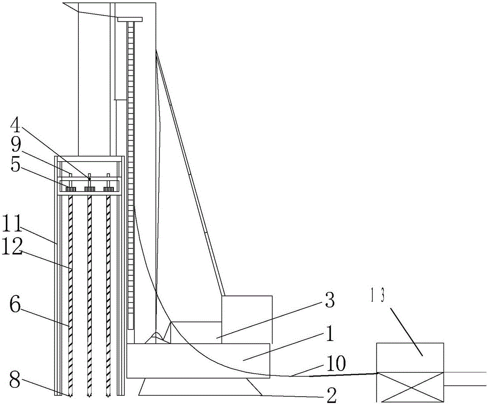
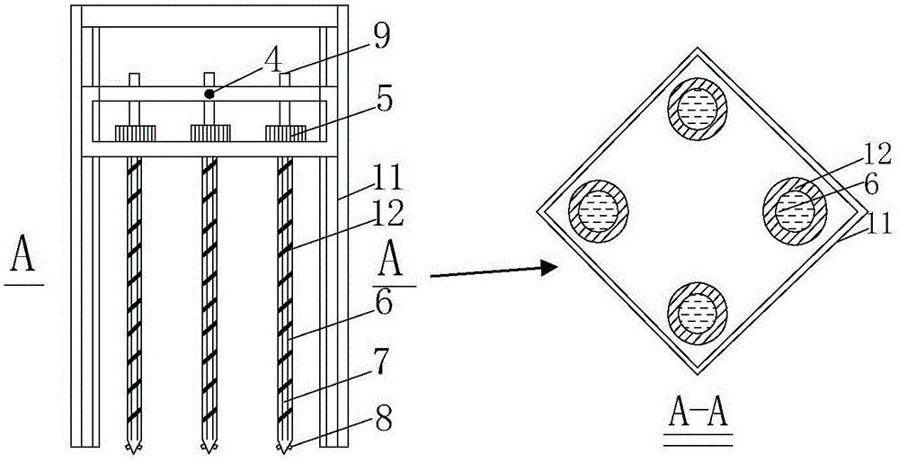
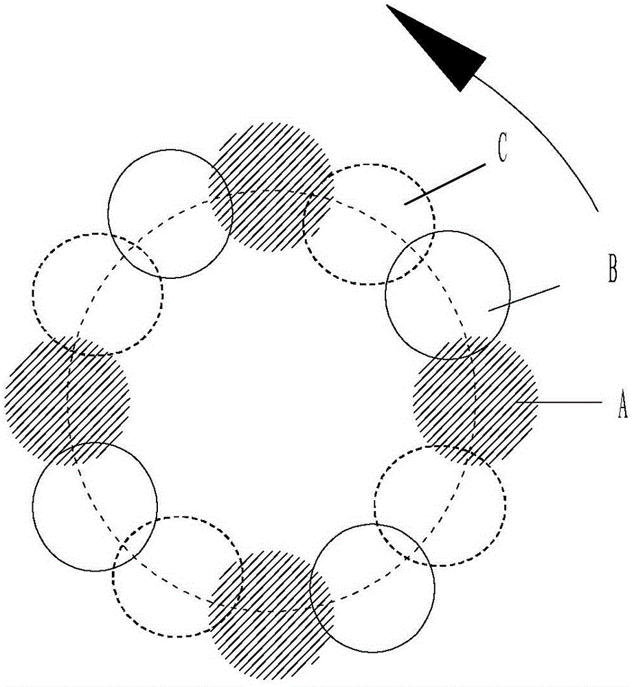
[0027] Such as figure 1 , 2 As shown in and 3, the winch 3 and the main engine 1 are located on the chassis 2, and the long auger rod 6 is fixed on the top of the positioning frame 11, and the positioning frame 11 is connected to the power unit 5 in rotation, and the positioning frame can be positioned after each construction. 11 rotation angles. The long auger rod 6 is a hollow structure, which is composed of a core pipe 7 and a helical blade 12. The top of the long auger rod 6 is provided with an exhaust valve 9, and the bottom is provided with a flap valve 8. Before the drilling tool cuts the soil, the flap valve 8. Close to prevent soil, sand or water from entering the auger core pipe 7, and open the flap valve 8 when pumping concrete. The arrangement of multi-axis drill pipes, the staggered side view of blades and the top view of A-A s...


PUM


Abstract

The invention discloses a multi-head minor-diameter long-spiral drilling machine. The multi-head minor-diameter long-spiral drilling machine comprises a main engine, a winding engine, a spiral drill pipe module, a locating rack, a powder device and a background concrete treatment system, wherein the winding engine is positioned on a base plate; 2-6 spiral drill pipes are symmetrically fixed on the top of the locating rack to form an annulus; during once drilling, the 2-6 spiral drill pipes work at the same time; the locating rack is connected with the power device in a rotating manner, so that the angle can be changed by rotation after construction every time. The multi-head minor-diameter long-spiral drilling machine has the following advantages that the head and tail of a long-spiral drill are annularly connected to form a cast-in-situ major-diameter tubular pile, and the inner and outer walls of the cast-in-situ major-diameter tubular pile are wavy, so that the contact area of the pipe with soil is greatly enlarged, and the side friction resistance of the pile is increased; as for the cast-in-situ major-diameter tubular pile, the problems that the soil compaction effect is increased due to the increased pile thickness, construction is difficult, and the like, are overcome, site construction soil compaction has relatively little influence on the ambient environment, and the problems like pile cutting are avoided; the construction cost is reduced, the construction technology is clear, the construction speed is high, the pile forming effect is good, the bearing capacity is high, and the construction cost is low.

Description

technical field [0001] The invention belongs to the technical field of civil engineering, and in particular relates to a multi-head small-diameter long auger and its application in the construction of cast-in-place large-diameter pipe piles. Background technique [0002] The long auger pile foundation has technical advantages such as fast construction speed and strong hole penetration ability. Before the present invention, the Chinese invention patent (patent number: ZL200610085598.4) disclosed a wall-forming method of a multi-head small-diameter long auger drilled into a wall-forming machine; this invention uses two or three augers arranged side by side on the gantry pile frame Rod, the drill bit is set at the lower end, the top is connected with the positioning frame, the positioning frame is slidingly connected with the gantry pile frame, the rotating power device is installed inside the positioning frame, the auger rod is connected with the rotating power device, the mid...

Claims


Application Information

Patent Timeline
Patent Type & Authority Applications(China)
IPC IPC(8): E02D5/36E21B7/02E21B17/22
Inventor 孔纲强周杨刘汉龙曹兆虎周航
Owner HOHAI UNIV
Learn More