
Method for preparing high-silicon silicon-manganese alloy

A technology for high silicon-silicon-manganese alloy and silicon-manganese water quenching slag is applied in the field of metal smelting, which can solve the problems of high production cost, high production difficulty, high production energy consumption, etc., and achieves high grade rate, strong product competitiveness and high production efficiency. The effect of reduced energy consumption

Inactive Publication Date: 2015-12-02
云南文山斗南锰业股份有限公司
View PDF2 Cites 3 Cited by
  • Summary
  • Abstract
  • Description
  • Claims
  • Application Information

AI Technical Summary

Problems solved by technology

In the prior art, the production of high-silicon-silicon-manganese has problems such as high requirements for raw materials, high production energy consumption, high production cost, difficult operation, and difficult production.

Method used


Image

  • Method for preparing high-silicon silicon-manganese alloy
  • Method for preparing high-silicon silicon-manganese alloy
  • Method for preparing high-silicon silicon-manganese alloy

Examples


Embodiment 1

[0042] In this example, under the same conditions of raw material composition and weight, the influence on smelting is compared between adding graphite carbon rods in the middle of the intermediate frequency furnace and not adding graphite carbon rods for fluxing.

[0043] 1. Experimental method

[0044] In this embodiment, the intermediate frequency furnace with graphite carbon rods for melting is used as the experimental group, and the intermediate frequency furnace without graphite carbon rods for melting is used as the control group. The specific preparation method is as follows:

[0045] (1) 40Kg of silicomanganese (manganese 66.38%, silicon 16.41) is smelted by submerged arc furnace to obtain liquid silicomanganese alloy;

[0046] (2) Utilize the intermediate frequency furnace to smelt 13Kg of ferrosilicon (manganese 0.4%, silicon 70%), and add 5Kg of silicon manganese water quenching slag to smelt when it turns red, and obtain liquid ferrosilicon alloy. Graphite carbon r...

Embodiment 2

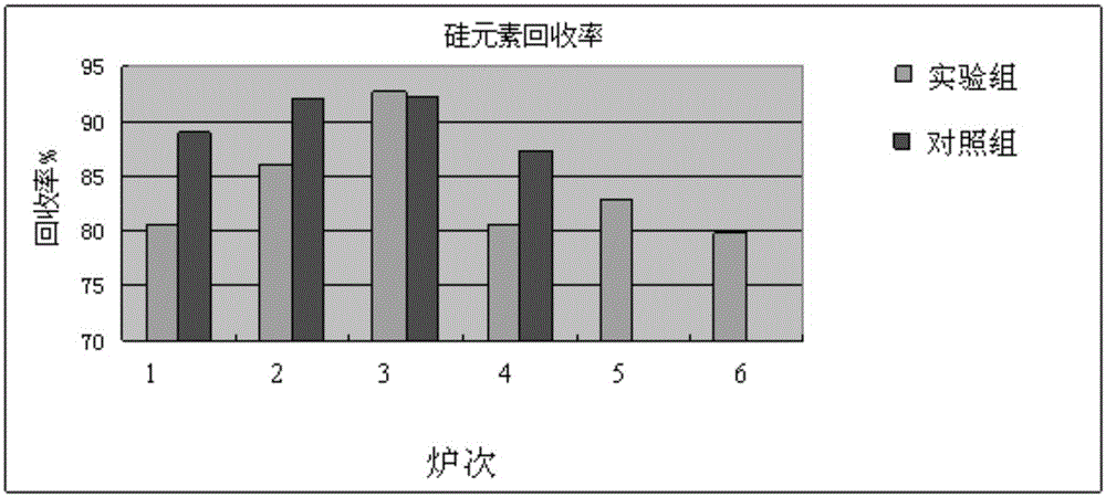
[0052] In this embodiment, industrial silicon is used as silicon-containing raw material, and the recovery rate of silicon element in industrial silicon and the recovery rate of each element in the alloy are detected.

[0053] 1. Experimental method:

[0054] (1) Utilize submerged arc furnace to smelt silicon-manganese and carbon-manganese, wherein, the addition of silicon-manganese and carbon-manganese is shown in Table 2, to obtain liquid silicon-manganese alloy;

[0055] (2) Utilize the industrial frequency furnace to smelt industrial silicon, and add silicomanganese water-quenched slag to smelt together when it turns red, wherein, the addition amount of industrial silicon and silicomanganese-manganese water-quenched slag is shown in Table 2 to obtain liquid ferrosilicon alloy;

[0056] (3) Add the liquid silicon manganese alloy into the industrial frequency furnace, mix it with the liquid silicon ferrosilicon alloy, and remelt it at 1650 degrees Celsius to obtain the high ...


PUM


Abstract

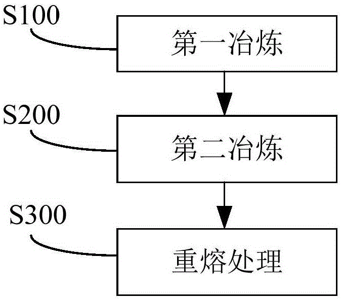
The invention discloses a method for preparing a high-silicon silicon-manganese alloy. According to the embodiment of the invention, a manganese-containing raw material is subjected to primary smelting to obtain a liquid-state non-standard manganese-silicon alloy; a silicon-containing raw material is subjected to secondary smelting to obtain a liquid-state silicon mixture, wherein in the secondary smelting, graphite carbon rods are used for fluxing; and the liquid-state non-standard manganese-silicon alloy and the liquid-state silicon mixture are subjected to alloying treatment to obtain the high-silicon silicon-manganese alloy. By using the method disclosed by the invention for producing the high-silicon silicon-manganese alloy, the coke consumption is low, the electricity consumption is low, the cost is remarkably reduced, and the obtained high-silicon silicon-manganese alloy is high in grade and product competitiveness; and moreover, by using the graphite carbon rods for fluxing during a smelting process, the smelting time is remarkably reduced, and the production energy consumption is further reduced.

Description

technical field [0001] The invention relates to the field of metal smelting, in particular to a method for preparing a high-silicon-silicon-manganese alloy. Background technique [0002] At present, ferroalloy products are affected by the iron and steel industry and the country's macroeconomic conditions, and more than 90% of the enterprises are in a state of huge losses. In this way, improving production efficiency and reducing production costs are important tasks that the iron and steel industry needs to solve. In the prior art, high-silicon-silicon-manganese production has problems such as high requirements for raw materials, high production energy consumption, high production cost, difficult operation, and relatively difficult production. [0003] Therefore, the method for preparing high-silicon-silicon-manganese alloys needs to be improved. Contents of the invention [0004] The present invention aims to solve at least one of the technical problems existing in the pr...

Claims


Application Information

Patent Timeline
IPC IPC(8): C22B4/06
Inventor 屠章云邢涛刘招俊蔡德鸿杨选韦祖林
Owner 云南文山斗南锰业股份有限公司
Learn More