
Rocker type suspension track for spreading machine

A paver and rack-type technology, which is applied to tracked vehicles, motor vehicles, transportation and packaging, etc., can solve the problems of insufficient response time, low impact frequency of supporting rollers, and small impact force momentum, etc., to improve machine performance Body stability, ensuring the grounding area, and reducing the effect of impact frequency

Active Publication Date: 2015-12-02
XCMG CONSTR MACHINERY
View PDF7 Cites 8 Cited by
  • Summary
  • Abstract
  • Description
  • Claims
  • Application Information

AI Technical Summary

Problems solved by technology

[0002] The fuselage, track beam and rollers of traditional paver are rigidly connected together by bolts. In conventional paving, due to the slow paving speed, the impact frequency of the road on the rollers is low, and the momentum of the impact force is also low. Smaller, less impact on the stability of the vehicle body, enough response time for leveling, little impact on the paved road surface, when the paver wants to achieve fast paving, the impact frequency and impact of the road on the rollers The force momentum will increase with the acceleration of the paving speed, and the vibration frequency and amplitude of the body will also increase. When the vibration frequency and amplitude reach a certain value, the leveling system will not have enough response time to adjust the screed attitude, the pavement quality will be greatly affected
[0003] It can be seen that the existing rigid connection between the track beam and the rollers cannot play a good role in shock absorption and buffering, so it is urgent to develop a new connection method

Method used


Image

  • Rocker type suspension track for spreading machine
  • Rocker type suspension track for spreading machine
  • Rocker type suspension track for spreading machine

Examples


Embodiment Construction

[0027] The present invention will be further described below in conjunction with accompanying drawing.

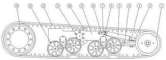
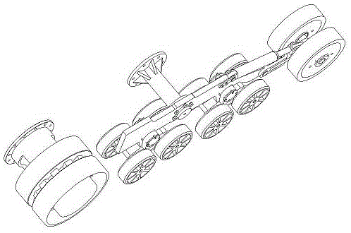
[0028] Such as figure 1 and figure 2 As shown, the present invention mainly consists of rubber track 12, and guide wheel 1 located in rubber track 12, guide wheel bracket system 2, drive wheel system 14, tension spring system 4, track beam 9, and the track beam 9 below Roller pendulum system 13 forms.

[0029] Such as Figure 8 and Figure 9 As shown, the crawler beam 9 plays the role of the overall skeleton and support, and is connected with the fuselage through the connecting frame 10 to support the fuselage.

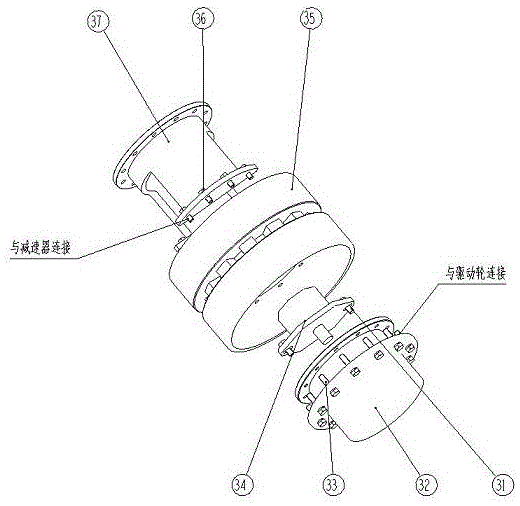
[0030] Such as image 3 As shown, the main function of the driving wheel system 14 is to drive the rubber track 12 to provide power for the whole system by rotating itself. Its main components include a driving wheel 35 , a reducer 34 , and a hydraulic motor 32 . Wherein: the hydraulic motor 32 is connected with the speed reducer 34 through the bolt 31 to pr...


PUM


Abstract

The invention discloses a rocker type suspension track for a spreading machine, comprising a rubber track (12) as well as a guide wheel (1), a guide wheel support system (2), a driving wheel system (14), a tension spring system (4), a track girder (9) and a thrust wheel rocker system (13) which are positioned in the rubber track (12), wherein the thrust wheel rocker system (13) is positioned below the track girder (9). The thrust wheel rocker system (13) is capable of realizing longitudinal oscillation so as to realize the functions of shock absorption and load bearing of a machine body; the driving wheel system (14) is capable of realizing the function of supplying power; and the guide wheel (1), the guide wheel support system (2) and the tension spring system (4) are capable of realizing the functions of transferring the power, tensioning the rubber track (12) and playing a partial buffer effect.

Description

technical field [0001] The invention relates to a swing-type suspension crawler belt, which is especially suitable for a paver. Background technique [0002] The fuselage, track beam and rollers of traditional paver are rigidly connected together by bolts. In conventional paving, due to the slow paving speed, the impact frequency of the road on the rollers is low, and the momentum of the impact force is also low. Smaller, less impact on the stability of the vehicle body, enough response time for leveling, little impact on the paved road surface, when the paver wants to achieve fast paving, the impact frequency and impact of the road on the rollers The force momentum will increase with the acceleration of the paving speed, and the vibration frequency and amplitude of the body will also increase. When the vibration frequency and amplitude reach a certain value, the leveling system will not have enough response time to adjust the screed The attitude of the pavement will be gre...

Claims


Application Information

Patent Timeline
IPC IPC(8): B62D55/10B62D55/112
Inventor 李骁斐朱振东王克冰李亮荣董金芳张旭光朱信强
Owner XCMG CONSTR MACHINERY
Learn More