Eureka AIR delivers breakthrough ideas for toughest innovation challenges, trusted by R&D personnel around the world.

Washing device for engineering vehicle

A technology for cleaning devices and engineering vehicles, which is applied to vehicle exterior cleaning devices, cleaning methods using liquids, cleaning methods and utensils, etc., can solve the problems of unusable equipment, difficult maintenance and cleaning, long connection lines, etc., to increase service life. and efficiency, reduce the size of the control system, and increase the effect of power protection

Inactive Publication Date: 2015-12-02
WUHU QUZHI ELECTRONICS TECH CO LTD
View PDF6 Cites 6 Cited by
  • Summary
  • Abstract
  • Description
  • Claims
  • Application Information

AI Technical Summary

Problems solved by technology

[0003] The structure of the traditional engineering car washing machine is a split type, the main body of the equipment and the control box are separated, and a long connection line is required in the middle, which is neither safe nor beautiful
[0004] The traditional control box is large in size and takes up a lot of space, which poses a certain safety hazard to the normal production and operation of the construction site
The control system has no safety protection measures, and the safety of electricity consumption cannot be guaranteed
[0005] When the traditional engineering car washing machine is in use, it can only wash the chassis and tires, and the body cannot achieve complete dust reduction and cleaning effects
If it is used for a long time, the phenomenon of sludge clogging will occur, the water inlet cannot be disassembled, and maintenance and cleaning are difficult, which will easily cause the equipment to be unusable

Method used


Image

  • Washing device for engineering vehicle
  • Washing device for engineering vehicle
  • Washing device for engineering vehicle

Examples


Embodiment Construction

[0030] In order to make the technical means and creative features realized by the present invention easy to understand, the present invention will be further elaborated below.

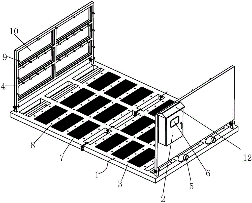
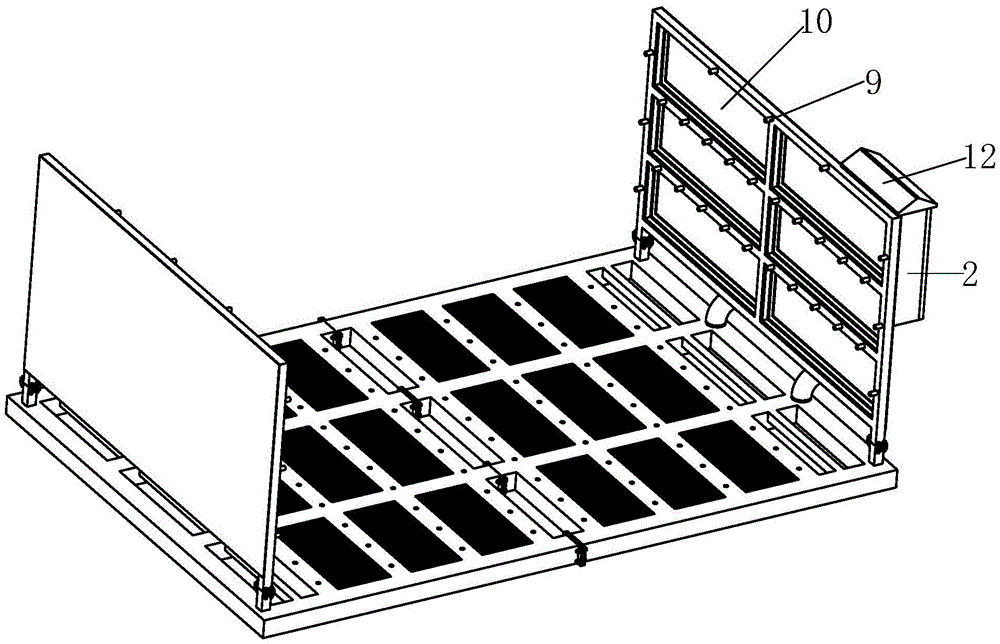
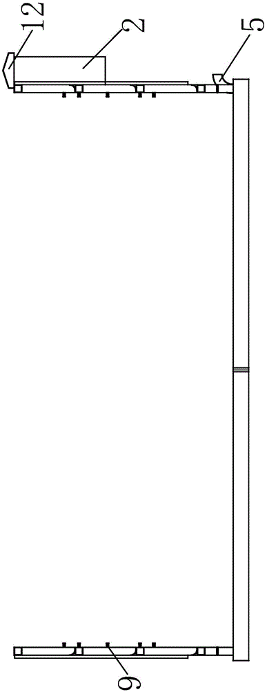
[0031] Such as Figure 1 to Figure 6 As shown, a cleaning device for engineering vehicles includes a frame 1 and a control box 2. The frame 1 includes a bottom plate 3 and side plates 4 fixedly installed on the left and right sides of the bottom plate 3 respectively. The inside of the bottom plate 3 is provided with a cavity structure, and the right side of the bottom plate 3 is installed with a water inlet 5 leading to the inner cavity of the bottom plate 3. The water inlet 5 is a hose interface, and the water inlet 5 is made of hard plastic reinforced pipe . Grid plates 7 are also laid on the base plate 3 , and a number of No. 1 nozzles 8 located between the grid plates 7 are evenly installed on the base plate 3 . The upper end surfaces of the No. 1 nozzles 8 are located below the upper end surface...


PUM

PropertyMeasurementUnit
Thicknessaaaaaaaaaa

Abstract

The invention relates to a washing device for an engineering vehicle. The washing device for the engineering vehicle comprises a frame and a control box, wherein the frame comprises a bottom plate and side plates, wherein the side plates are correspondingly and fixedly mounted on the left side and right side of the bottom plate, respectively; a cavity structure is arranged in the bottom plate; a water inlet leading to a cavity in the bottom plate is formed in the right side of the bottom plate; grid plates are also laid on the bottom plate; a plurality of No. 1 nozzles, which are positioned between the grid plates, are uniformly mounted on the bottom plate; the upper end surfaces of the No. 1 nozzles are all positioned below the upper end surfaces of the grid plates; cavities in the side plates are both communicated with the cavity in the bottom plate; and No. 2 nozzles are arranged on the internal side surfaces of the side plates. According to the washing device for the engineering vehicle, provided by the invention, problems that a traditional engineering vehicle washing machine is inconvenient to control, the use safety of the machine is substandard, the machine is hard for a manager to monitor and so on are solved; and the volume of a control system is reduced. As electric protection means is additionally provided, the washing device for the engineering vehicle, provided by the invention, is safe, stable and reliable. As a movable port is adopted at the water inlet, the washing device for the engineering vehicle, provided by the invention, is convenient to self-clean and favorable for prolonging the service life and increasing the efficiency.

Description

technical field [0001] The invention relates to the technical field of cleaning equipment for engineering vehicles, in particular to a cleaning device for engineering vehicles. Background technique [0002] The traditional engineering car washing machine mainly consists of a control system, an induction system, a water supply system, a transmission system, a water spray system and a frame. The vehicle slowly enters the car washing machine, and the sensing system detects the vehicle and sends a signal to the control system, and then the control system controls the water supply system and the transmission system to start working to complete the cleaning of the vehicle. [0003] The structure of the traditional engineering car washing machine is a split type, the main body of the equipment and the control box are separated, and a long connection line is required in the middle, which is neither safe nor beautiful. [0004] The traditional control box is large in size and takes ...

Claims


Application Information

Patent Timeline
IPC IPC(8): B60S3/04B08B3/02B08B13/00
Inventor 张朋军李辉
Owner WUHU QUZHI ELECTRONICS TECH CO LTD
Why Eureka
Eureka Blog
Learn More