Low pressure non-runner glue injection device

A technology of glue injection device and no runner, applied in the field of low-pressure glue injection device without runner, can solve the problems of manual removal, affect product quality, increase waiting time, etc., so as to reduce waste of glue material, save production time, and speed up molding effect of cycles

Active Publication Date: 2018-11-09
SUZHOU KONIG ELECTRONICS TECH CO LTD
View PDF3 Cites 0 Cited by
  • Summary
  • Abstract
  • Description
  • Claims
  • Application Information

AI Technical Summary

Problems solved by technology

[0002] First of all, the mold of the current low-pressure glue injection process is separated from the glue gun of the glue injection machine. The glue is injected into the packaged product from the glue gun through the mouth of the runner. When the glue flows through the mouth of the runner, pressure and temperature loss occur. , affecting product quality, and the raw materials for low-pressure injection injection cannot be reused. When the amount of glue used in the packaging product is less than the amount of glue used in the flow channel, the cost of the packaging product is greatly increased;
[0003] Secondly, the current low-pressure glue injection process needs to manually remove the glue mouth flow channel after the glue injection is completed, which increases the production man-hour of the packaged product;
[0004] Furthermore, the current low-pressure injection process needs to wait for the runner to cool before opening the mold, which increases the waiting time and reduces the utilization rate and production efficiency of the equipment.

Method used


Image

  • Low pressure non-runner glue injection device
  • Low pressure non-runner glue injection device

Examples


Embodiment Construction

[0019] Below in conjunction with the embodiment shown in the accompanying drawings, the present invention is described in detail as follows:

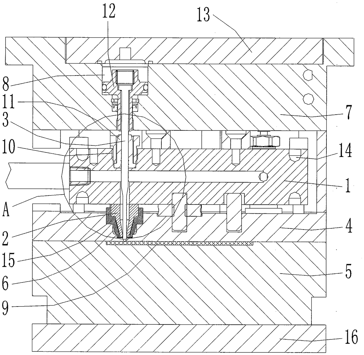
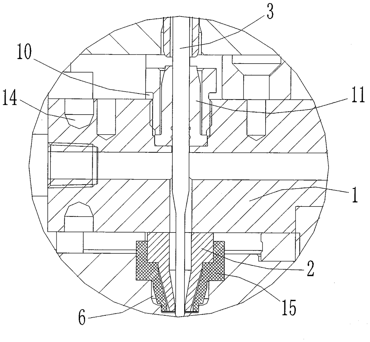
[0020] as attached figure 1 and attached figure 2 As shown, a low-pressure non-runner glue injection device includes a glue injection part and a mold part, and the glue injection part includes a glue gun body 1 with a cavity inside, and a cavity corresponding to the glue gun body 1 The penetrating gun nozzle 2, the valve needle 3 used to control the glue discharge from the gun nozzle 2, and the driving part used to drive the valve needle 3 to move, the glue gun body 1 has an internal cavity The connected glue outlet channel, part of the valve needle 3 is located in the gun nozzle 2 and the glue outlet channel, and the outside of the glue gun body 1 is provided with heating components; the mold part includes The upper template 4 and the lower template 5 for clamping and positioning the packaged product 9, the upper template 4 is provi...


PUM


Abstract

The invention discloses a low pressure glue injecting device without flow channel. The glue injecting device comprises a glue injecting part and a mold part, wherein the glue injecting part comprises a glue gun with an internal hollow cavity, a gun nozzle which is communicated with the hollow cavity of the glue gun, a valve needle for controlling the glue from the gun nozzle and a driving part for driving the action of the valve needle, a glue out channel communicated with the internal hollow cavity is arranged on the glue gun, part of the valve needle is arranged in the gun nozzle and the glue out channel and a heating part is arranged on the outer part of the glue gun; the mold part comprises an upper mold and a lower mold which are used for clamping and positioning a packaging product, a positioning through hole is formed in the upper mold, the gun nozzle is arranged in the positioning through hole, the glue gun is arranged on the upper mold, a panel is arranged on the upper mold, and a glue outlet of the gun nozzle directs to the packaging product. The flow channel and a glue nozzle are not needed in the design, the glue injecting part is integrated on the mold part, so as to prevent the flow channel and the glue nozzle from affecting the technology effect, reduce the glue injection pressure and the glue injection temperature, and facilitate to increase the efficiency and yield.

Description

technical field [0001] The invention relates to the field of low-pressure glue injection, in particular to a low-pressure non-runner glue injection device. Background technique [0002] First of all, the mold of the current low-pressure glue injection process is separated from the glue gun of the glue injection machine. The glue is injected into the packaged product from the glue gun through the mouth of the runner. When the glue flows through the mouth of the runner, pressure and temperature loss occur. , affecting product quality, and the raw materials for low-pressure injection injection cannot be reused. When the amount of glue used in the packaging product is less than the amount of glue used in the flow channel, the cost of the packaging product is greatly increased; [0003] Secondly, the current low-pressure glue injection process needs to manually remove the glue mouth flow channel after the glue injection is completed, which increases the production man-hour of the...

Claims


Application Information

Patent Timeline
Patent Type & Authority Patents(China)
IPC IPC(8): B29C45/20B29C45/26
CPCB29C45/20B29C45/26B29C2045/205
Inventor 朱建晓
Owner SUZHOU KONIG ELECTRONICS TECH CO LTD
Why Eureka
Try Eureka