Integrated friction stir welding equipment

A technology of friction stir welding and equipment, which is applied in the direction of welding equipment, non-electric welding equipment, metal processing equipment, etc., and can solve the problems that the automatic processing of welding and forming cannot be realized.

Inactive Publication Date: 2015-12-02
昆山斯格威电子科技有限公司
View PDF6 Cites 0 Cited by
  • Summary
  • Abstract
  • Description
  • Claims
  • Application Information

AI Technical Summary

Problems solved by technology

The difference is. The friction stir welding welding process is that a cylindrical welding head (welding pin) is inserted into the joint of the workpiece, and through the high-speed rotation of the welding head, it is rubbed against the material of the welding workpiece, so that the temperature of the material at the joint is increased and softened . At the same time, friction stir is performed on the material to complete the welding. At the end of the friction stir welding, a keyhole will be left at the welding end. Usually, this keyhole can be cut off, or it can be sealed and welded by other welding methods, that is, the friction stir welding is completed. Afterwards, other equipment and methods need to be used to process the keyhole, so it is impossible to realize the automatic processing of the entire welding molding

Method used


Image

  • Integrated friction stir welding equipment

Examples


Embodiment Construction

[0013] The present invention will be further described below in conjunction with the accompanying drawings. The following examples are only used to illustrate the technical solution of the present invention more clearly, but not to limit the protection scope of the present invention.

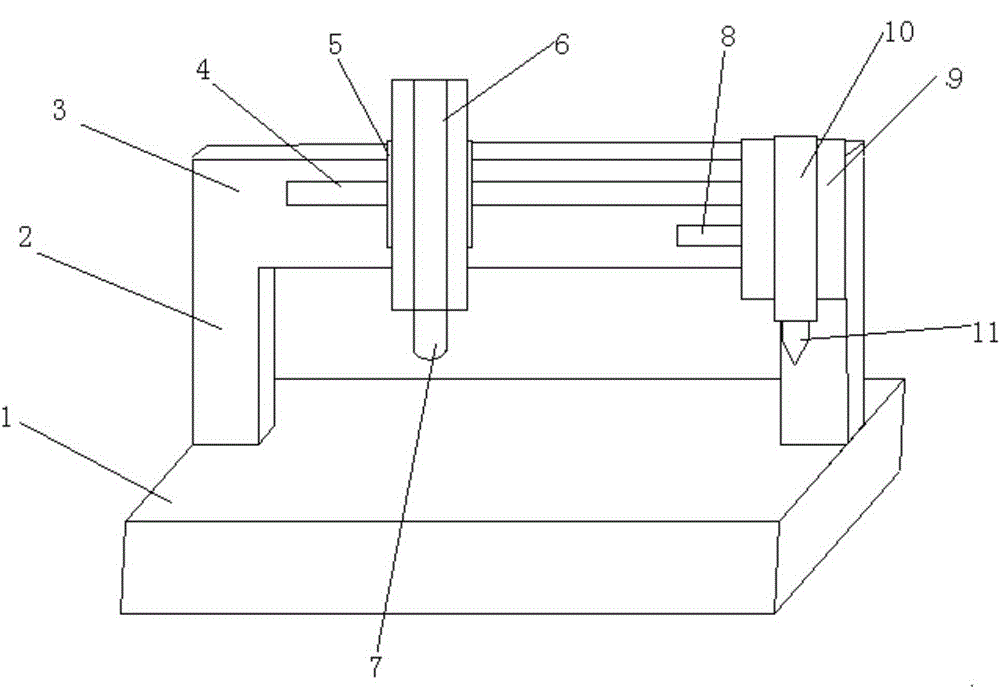
[0014] like figure 1 The shown integrated friction stir welding equipment includes a welding table 1, a gate-shaped frame is arranged on the welding table 1, the frame includes a column 2 and a beam 3, and a guide rail 1 is fixed laterally on the beam 3 4. One end of the guide rail one 4 is fixed with a drive device one, and the drive device one is connected with the slide table one 5 on the guide rail one 4 through a connecting rod one, and the slide table one 5 is fixed with a vertical spring Device one 6, the friction stir welding head 7 is connected to the bottom of the vertical springing device one 6; the guide rail two 8 is arranged in parallel below the guide rail one 4, and the end of t...


PUM


Abstract

The invention discloses integrated friction stir welding equipment which comprises a welding table. A portal frame is arranged on the welding table and comprises a stand column and a cross beam. A first guide rail is transversely fixed to the cross beam. A first driving device is connected with a first sliding table on the first guide rail through a first connecting rod. A first vertical springing device is fixed to the first sliding table. A friction stir welding machine head is connected to the bottom of the vertical springing device. A second guide rail is arranged below the first guide rail in parallel. The tail end of the second guide rail exceeds the tail end of the first guide rail. A second driving device is connected with a second sliding table on the second guide rail through a second connecting rod. A second vertical springing device is fixed to the second sliding table. A fusion welding gun head is connected to the bottom of the second vertical springing device. The integrated friction stir welding equipment can automatically carry out friction stir welding and key hole filling in a controllable mode, and is suitable for being applied in the welding process.

Description

technical field [0001] The invention relates to a friction stir welding equipment, in particular to an integrated friction stir welding equipment. Background technique [0002] Friction stir welding (Friction Stir Welding) is a patented welding technology proposed by The Welding Institute in the United Kingdom. The friction stir welding method is the same as conventional friction welding. Friction stir welding also uses friction heat as a welding heat source. The difference is. The friction stir welding welding process is that a cylindrical welding head (welding pin) is inserted into the joint of the workpiece, and through the high-speed rotation of the welding head, it is rubbed against the material of the welding workpiece, so that the temperature of the material at the joint is increased and softened . At the same time, friction stir is performed on the material to complete the welding. At the end of the friction stir welding, a keyhole will be left at the welding end...

Claims


Application Information

Patent Timeline
Patent Type & Authority Applications(China)
IPC IPC(8): B23K20/12
CPCB23K20/122
Inventor 蔡智亮沈金华赵刚李彦国杨洪刚赵欣裴冠宏康荣峰
Owner 昆山斯格威电子科技有限公司
Why Eureka
Try Eureka