
Alternating-current phasor analysis method and modeling method for phase-shifting control dual active bridge direct-current converters

A DC converter, dual active bridge technology, applied in the direction of converting DC power input to DC power output, adjusting electrical variables, controlling/regulating systems, etc. Universal model, unclear physical meaning, etc., to achieve the effect of clear physical meaning, simplified calculation, and simple operation

Inactive Publication Date: 2015-11-25
CHINA UNIV OF MINING & TECH (BEIJING)
View PDF6 Cites 33 Cited by
  • Summary
  • Abstract
  • Description
  • Claims
  • Application Information

AI Technical Summary

Problems solved by technology

Its main disadvantages are that the calculation is complicated, the physical meaning is not clear, and the analysis results cannot directly reflect the relationship between transmission power and reactive power, and the traditional analysis method for various phase shifting methods cannot establish a general model

Method used


Image

  • Alternating-current phasor analysis method and modeling method for phase-shifting control dual active bridge direct-current converters
  • Alternating-current phasor analysis method and modeling method for phase-shifting control dual active bridge direct-current converters
  • Alternating-current phasor analysis method and modeling method for phase-shifting control dual active bridge direct-current converters

Examples


Embodiment Construction

[0061] Below in conjunction with accompanying drawing and specific embodiment with figure 1 The shown dual active H-bridge DC converter topology is taken as an example to further illustrate the present invention.

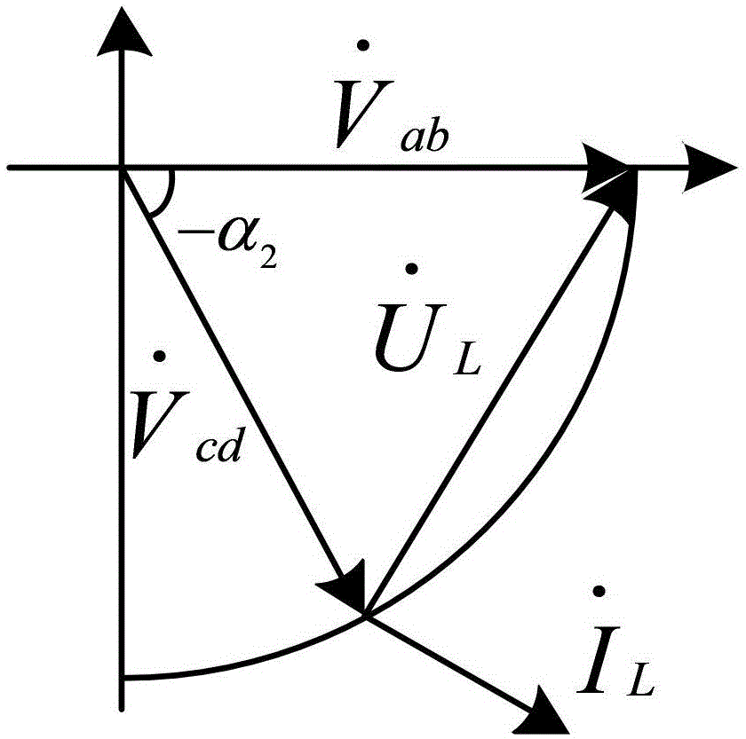
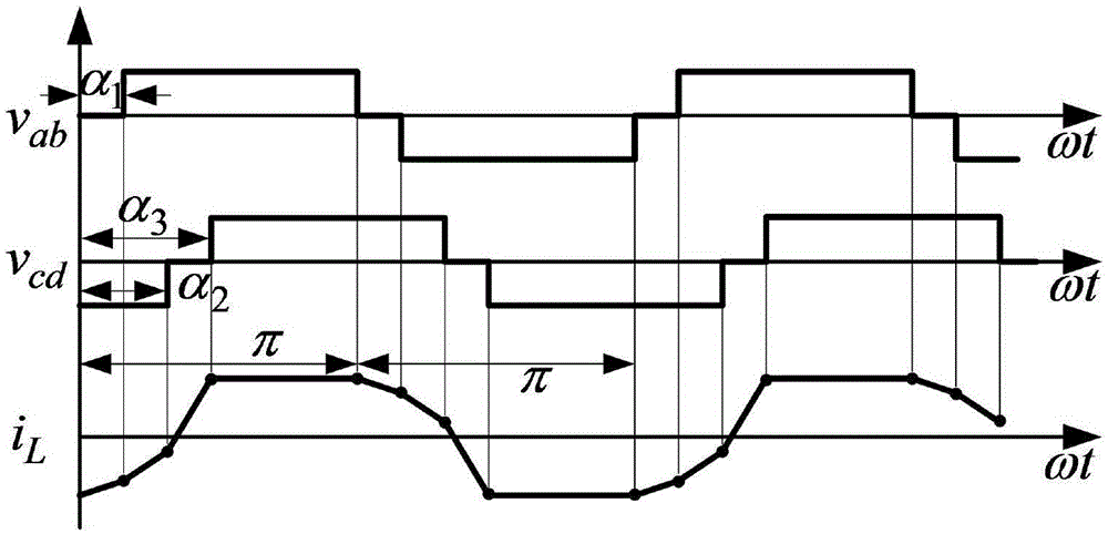
[0062] image 3 Shown are three phase-shift control strategies: single phase-shift, extended phase-shift, double phase-shift control ideal waveform diagram; among them, V ab (t), V cd (t) is the AC side square wave voltage of two single-phase H-bridges, with the phase of the driving signal S1 as the reference phase, the phase delay between the driving signal S4 and S1 is called the inner phase angle α of H1 1 ; The phase delay between the driving signal Q1 and S1 is called the external phase angle α 2 ; The phase delay between the driving signal Q4 and S1, that is, the internal phase shift angle α of H2 4 and external phase angle α 2 The sum is called α 3 (α 3 = α 2 +α 4 ).

[0063] Taking H1 ahead of H2 as an example, three phase-shift control strategies ...


PUM


Abstract

The invention provides alternating-current phasor analysis method and small signal model modeling method suitable for dual-active bridge (dual active H bridges, dual three-level half bridges or a three-level half bridge on one side and an active H bridge on the other side and the like) direct-current converters in all phase-shifting controls. The alternating-current phasor analysis method and small signal model modeling method comprise the specific steps as follows: (1) an alternating current side of each active bridge is equivalent to two square-wave voltage sources through equivalence, and square-wave voltage is decomposed into superposition of sinusoidal voltage through Fourier series decomposition to obtain phasor expressions, as shown in the specification, of (2n+1)th component voltage and inductive current; (2) phasor diagrams of control characteristics and control ranges under different phase-shifting controls are obtained according to the phasor expressions in the step 1; (3) complex power, as shown in the specification, of the (2n+1)th component is obtained according to the phasor expressions in the step 1, and active and reactive power characteristics of the dual-active bridge direct-current converters under different phase-shifting controls are analyzed; and (4) time domain Fourier series and expressions of the voltage and the current are obtained according to the phasor expressions in the step 1, so as to obtain a unified signal model suitable for all phase-shifting control methods.

Description

technical field [0001] The invention belongs to the field of power electronics technology and smart grid research, and in particular relates to a phase shift control dual active bridge circuit power analysis method and modeling based on a phasor method. Background technique [0002] With the development of smart grids, high-power power electronic converters without power frequency transformers have attracted more and more attention due to their high efficiency, intelligence, and low pollution. At present, the common high-power power electronic converter without industrial frequency transformer adopts cascaded topology, which is composed of cascaded multi-level AC-DC rectification module, bidirectional DC-DC conversion module and multi-level DC-AC inverter module. [0003] The dual active bridge DC-DC converter structure is adopted by the bidirectional DC-DC conversion module due to its characteristics of electrical isolation, buck-boost conversion, bidirectional energy trans...

Claims


Application Information

Patent Timeline
IPC IPC(8): H02M3/335G06F19/00
Inventor 王聪沙广林王健宇胡小菊马志鹏程红王俊庄园王浩
Owner CHINA UNIV OF MINING & TECH (BEIJING)
Learn More