A motor rotor and stator assembly device and assembly method
A technology of rotor stator and motor rotor, which is used in electromechanical devices, manufacturing motor generators, electrical components, etc., can solve problems such as elastic deformation, low tensile force, and unstable operation.
- Summary
- Abstract
- Description
- Claims
- Application Information
AI Technical Summary
Problems solved by technology
Method used
Image

Examples
Embodiment 1
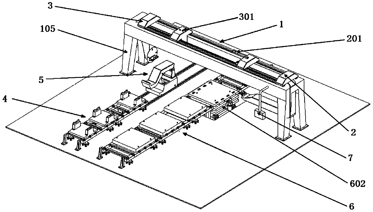
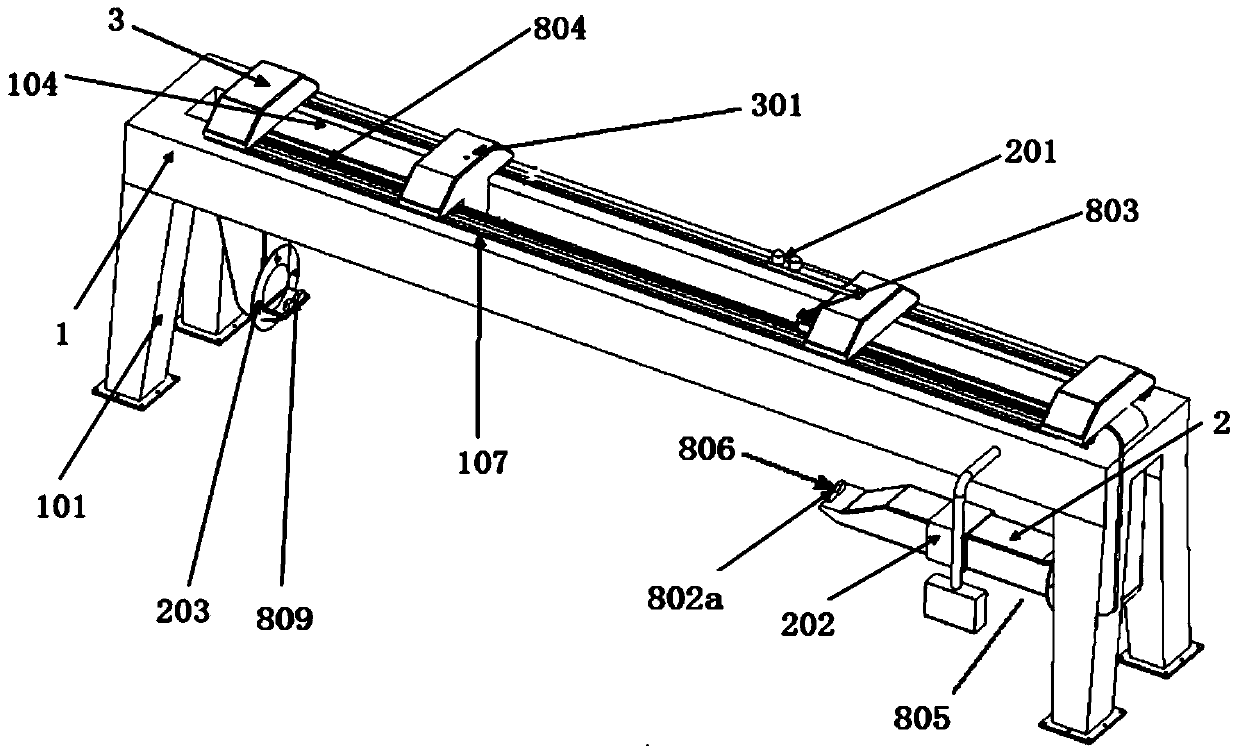
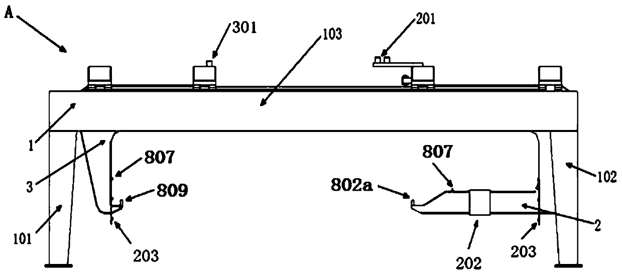
[0100] like figure 1 , a motor rotor and stator assembly device, including cantilever beam assembly machine A, rotor assembly line 4, stator assembly line 6, suspension beam assembly machine A includes a main beam device 1, a U-shaped main suspension beam 2 placed horizontally on the right and a L horizontally placed on the left Type auxiliary suspension beam 3, rotor assembly line 4 includes rotor input assembly line 401, stator assembly line 6 includes stator input assembly line 601, stator center adjustment platform 602, rotor stator assembly output assembly line 603, U-shaped main suspension beam 2 is provided with stator assembly line 6, L A rotor assembly line 4 is arranged under the secondary suspension beam 3, and the ends or front ends of the respective brackets 805 of the horizontal U-shaped main suspension beam 2 and the horizontal L-shaped secondary suspension beam 3 respectively have support openings 809 opposite to each other, and the two support openings are resp...
Embodiment 2
[0106] like figure 1 , a motor rotor and stator assembly device, including cantilever beam assembly machine A, rotor assembly line 4, stator assembly line 6, suspension beam assembly machine A includes a main beam device 1, a U-shaped main suspension beam 2 placed horizontally on the right and a L horizontally placed on the left Type auxiliary suspension beam 3, rotor assembly line 4 includes rotor input assembly line 401, stator assembly line 6 includes stator input assembly line 601, stator center adjustment platform 602, rotor stator assembly output assembly line 603, U-shaped main suspension beam 2 is provided with stator assembly line 6, L A rotor assembly line 4 is arranged under the secondary suspension beam 3, and the ends or front ends of the respective brackets 805 of the horizontal U-shaped main suspension beam 2 and the horizontal L-shaped secondary suspension beam 3 respectively have support openings 809 opposite to each other, and the two support openings are resp...
Embodiment 3
[0112] Repeating Example 1, the device also includes a fully automatic electrical appliance control system 7 . The automatic electrical control system 7 is connected with the cantilever assembly machine A, the rotor assembly line 4, the stator assembly line 6, and the rotor loading trolley assembly line 5. And detect and control the cantilever assembly machine A, the rotor assembly line 4, the stator assembly line 6, and the rotor loading trolley assembly line 5.
PUM
 Abstract
Description
Claims
Application Information
 - R&D
- Intellectual Property
- Life Sciences
- Materials
- Tech Scout
- Unparalleled Data Quality
- Higher Quality Content
- 60% Fewer Hallucinations
Browse by: Latest US Patents, China's latest patents, Technical Efficacy Thesaurus, Application Domain, Technology Topic, Popular Technical Reports.
© 2025 PatSnap. All rights reserved.Legal|Privacy policy|Modern Slavery Act Transparency Statement|Sitemap|About US| Contact US: help@patsnap.com