


Quick Research
Generate reliable direction feasibility study reports for your R&D in just a few steps.

Technical Q&A
Discover and master advanced knowledge NOW. Basics, ideas, possibilities, all at once.

Find Solutions
As an expert in R&D theories, this can generate solutions to your technical problems instantly.

Evaluate Feasibility
Analyze your overall solution with one click, know your potential R&D risks in advance.

Monitor Landscape
Get weekly tech updates, stay abreast of the latest tech innovations and key insights.
Attaching device and attaching method for motor rotor and stator
A motor rotor, rotor stator technology, applied in the direction of electromechanical devices, manufacturing motor generators, electrical components, etc., can solve problems such as failure to meet multiple specifications and types of motors, damage to the rotor insulation layer, and suspension beams that cannot freely adjust the upper and lower positions.
- Summary
- Abstract
- Description
- Claims
- Application Information
AI Technical Summary
Problems solved by technology
Method used
Image

Examples
Embodiment 1
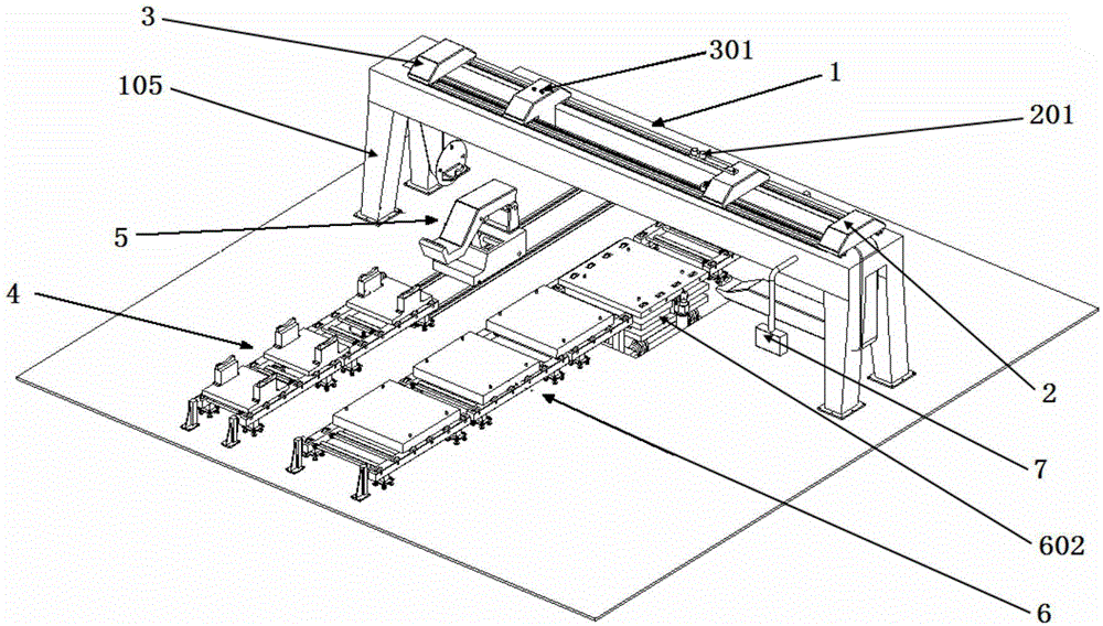
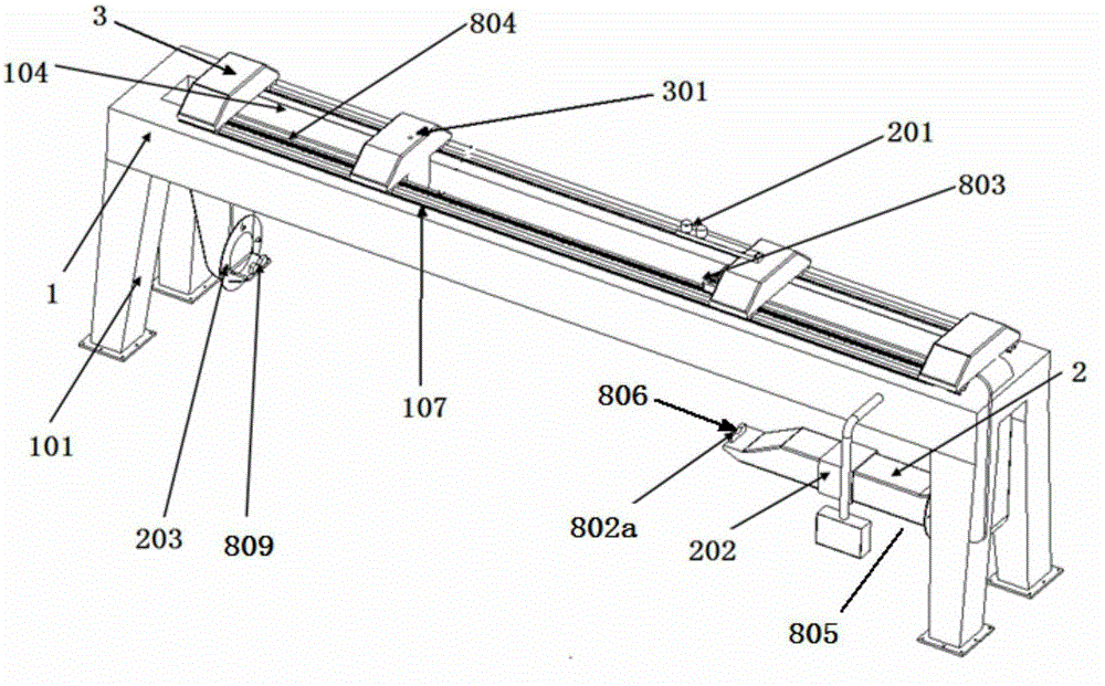
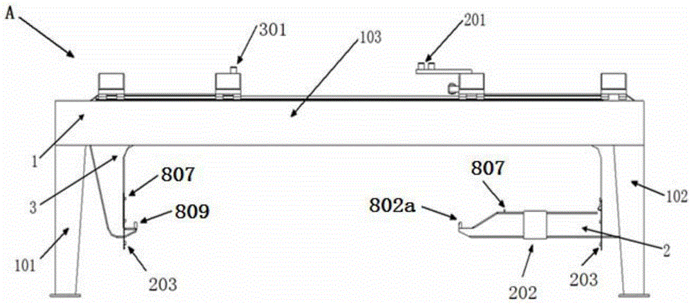
[0100] Such as figure 1 , a motor rotor and stator assembly device, including cantilever beam assembly machine A, rotor assembly line 4, stator assembly line 6, suspension beam assembly machine A includes a main beam device 1, a U-shaped main suspension beam 2 placed horizontally on the right and an L horizontally placed on the left Type auxiliary suspension beam 3, rotor assembly line 4 includes rotor input assembly line 401, stator assembly line 6 includes stator input assembly line 601, stator center adjustment platform 602, rotor stator assembly output assembly line 603, U-shaped main suspension beam 2 is provided with stator assembly line 6, L A rotor assembly line 4 is arranged under the secondary suspension beam 3, and the ends or front ends of the respective brackets 805 of the horizontal U-shaped main suspension beam 2 and the horizontal L-shaped secondary suspension beam 3 respectively have support openings 809 opposite to each other, and the two support openings are ...
Embodiment 2
[0106] Such as figure 1 , a motor rotor and stator assembly device, including cantilever beam assembly machine A, rotor assembly line 4, stator assembly line 6, suspension beam assembly machine A includes a main beam device 1, a U-shaped main suspension beam 2 placed horizontally on the right and a L horizontally placed on the left Type auxiliary suspension beam 3, rotor assembly line 4 includes rotor input assembly line 401, stator assembly line 6 includes stator input assembly line 601, stator center adjustment platform 602, rotor stator assembly output assembly line 603, U-shaped main suspension beam 2 is provided with stator assembly line 6, L A rotor assembly line 4 is arranged under the secondary suspension beam 3, and the ends or front ends of the respective brackets 805 of the horizontal U-shaped main suspension beam 2 and the horizontal L-shaped secondary suspension beam 3 respectively have support openings 809 opposite to each other, and the two support openings are r...
Embodiment 3
[0112] Repeating Example 1, the device also includes a fully automatic electrical appliance control system 7 . The automatic electrical control system 7 is connected with the cantilever assembly machine A, the rotor assembly line 4, the stator assembly line 6, and the rotor loading trolley assembly line 5. And detect and control the cantilever assembly machine A, the rotor assembly line 4, the stator assembly line 6, and the rotor loading trolley assembly line 5.
PUM
 Abstract
Description
Claims
Application Information
 - R&D Engineer
- R&D Manager
- IP Professional
- Industry Leading Data Capabilities
- Powerful AI technology
- Patent DNA Extraction
Browse by: Latest US Patents, China's latest patents, Technical Efficacy Thesaurus, Application Domain, Technology Topic, Popular Technical Reports.
© 2024 PatSnap. All rights reserved.Legal|Privacy policy|Modern Slavery Act Transparency Statement|Sitemap|About US| Contact US: help@patsnap.com