
High-performance permanent magnet servo motor

A permanent magnet servo motor, high-performance technology, applied in the direction of magnetic circuit static parts, magnetic circuit rotating parts, magnetic circuit shape/style/structure, etc., can solve the problem of no-load phase sinusoidal back electromotive force, reduce Motor running performance and other issues, to achieve the effect of heat dissipation, stable motor operation, and lower temperature rise

Inactive Publication Date: 2015-11-25
SHANGHAI MOTOR SYST ENERGY SAVING ENG TECH RES CENT +2
View PDF10 Cites 7 Cited by
  • Summary
  • Abstract
  • Description
  • Claims
  • Application Information

AI Technical Summary

Problems solved by technology

The patent application number is 201210419454.3, which mentions a built-in permanent magnet motor rotor punch and a built-in permanent magnet motor rotor. The rotor magnetic circuit structure of this scheme can effectively avoid the magnetic flux leakage at the magnetic isolation bridge, so that the same amount of The air-gap magnetic field strength generated by the permanent magnet is greater, which reduces the manufacturing cost, but its magnetic circuit structure still cannot solve the problem of the no-load phase sinusoidal back electromotive force, especially the influence of the quadrature-axis armature reaction magnetic field on the direct-axis magnetic circuit. Without consideration, it will reduce the running performance of the motor at high speed

Method used


Image

  • High-performance permanent magnet servo motor

Examples


Embodiment 1

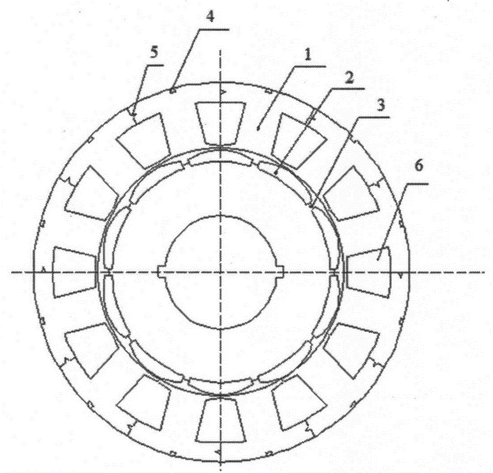
[0025] Such as figure 1 As shown, the high-performance permanent magnet servo motor of this embodiment includes a stator and a rotor, the stator includes a stator core and coils wound on the stator core, and the rotor includes a rotor core and a The permanent magnet 2 on the outer circumference, the stator iron core is formed by lamination of stator punching pieces, the stator punching piece is a split tooth structure, and is formed by splicing 12 stator tooth punching pieces 1, and the rotor The iron core is formed by lamination of rotor punching sheets, and permanent magnet slots are formed on the outer periphery of the rotor iron core. The permanent magnets 2 are in the shape of unequal thickness, and are embedded in the permanent magnet slots. The surface of the permanent magnets Glue is applied to both the permanent magnet slot and the permanent magnet slot for reinforcement. The outer sides of the rotor core and the permanent magnet 2 are provided with plastic seals, an...

Embodiment 2

[0030] The difference between this embodiment and Embodiment 1 is that the stator core has a half-open slot structure, and its opening is formed on the inner circumference of the stator core, which can effectively improve the air gap magnetic field distribution, reduce harmonic loss, and The cogging torque is greatly reduced, so that the output torque fluctuation of the permanent magnet servo motor meets the accuracy requirements.


PUM


Abstract

The invention provides a high-performance permanent magnet servo motor, which comprises a stator and a rotor, wherein the stator comprises a stator core and a coil; the coil is wound on the stator core; the rotor comprises a rotor core and a permanent magnet; the permanent magnet is arranged on the periphery of the rotor core; the high-performance permanent magnet servo motor is characterized in that the stator core is formed by laminating stator punching plates; each stator punching plate is formed by splicing at least two stator tooth punching plates; the rotor core is formed by laminating rotor punching plates; a permanent magnet groove is formed in the periphery of the rotor core; and the permanent magnet is embedded into the permanent magnet groove. According to the high-performance permanent magnet servo motor, improvement of the utilization rate of a silicon steel sheet is facilitated; the offline production rate is improved; the slot space-factor can be improved; the coils in a slot are arranged regularly and densely; and heat dissipation of the coils is facilitated.

Description

technical field [0001] The invention relates to the field of design and manufacture of a high-performance permanent magnet servo motor, in particular to the field of high-precision mechanical process equipment such as machine tools and electronic manufacturing, which have strict requirements on volume and weight. Background technique [0002] With the improvement of permanent magnet performance and price reduction, as well as the rapid development of power electronic control technology and microelectronic device development technology, permanent magnet servo control system has been developed rapidly. A series of advantages brought about by replacing the rotor winding in the wound rotor with permanent magnets, such as no heating problem of the rotor, simple control system, small size, light weight, high power density, high operating efficiency and high Running speed, etc., make permanent magnet synchronous servo motors widely used in high-performance and high-precision motion...

Claims


Application Information

Patent Timeline
Patent Type & Authority Applications(China)
IPC IPC(8): H02K1/12H02K1/27
Inventor 曹翼
Owner SHANGHAI MOTOR SYST ENERGY SAVING ENG TECH RES CENT
Learn More