CUP structure preventing high-pressure water mist splashing

A water mist and high-pressure technology, applied in the field of CUP structure, can solve the problems of high equipment cost, large process chamber volume, unfavorable machine miniaturization and cost control, and achieve low processing and installation costs, transparent appearance, and easy equipment maintenance Effect

Active Publication Date: 2015-11-25
SHENYANG KINGSEMI CO LTD
View PDF5 Cites 4 Cited by
  • Summary
  • Abstract
  • Description
  • Claims
  • Application Information

AI Technical Summary

Problems solved by technology

Although this fully enclosed cavity structure can realize the function of preventing high-pressure water mist, but because the movement mechanism and the liquid supply mechanism need to be enclosed in the cavity, this causes problems such as the volume of the process cavity is too large and the equipment cost is high. , which is not conducive to the miniaturization and cost control of the machine

Method used


Image

  • CUP structure preventing high-pressure water mist splashing
  • CUP structure preventing high-pressure water mist splashing
  • CUP structure preventing high-pressure water mist splashing

Examples


Embodiment Construction

[0023] The present invention will be described in further detail below in conjunction with the accompanying drawings.

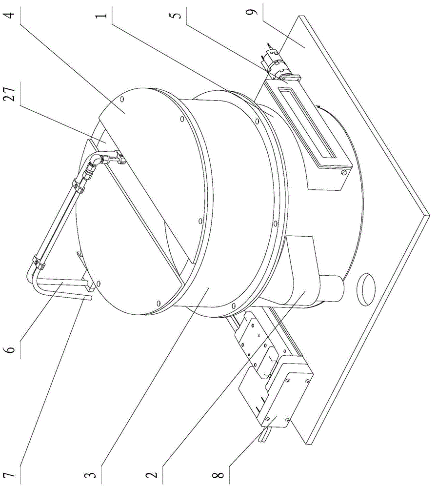
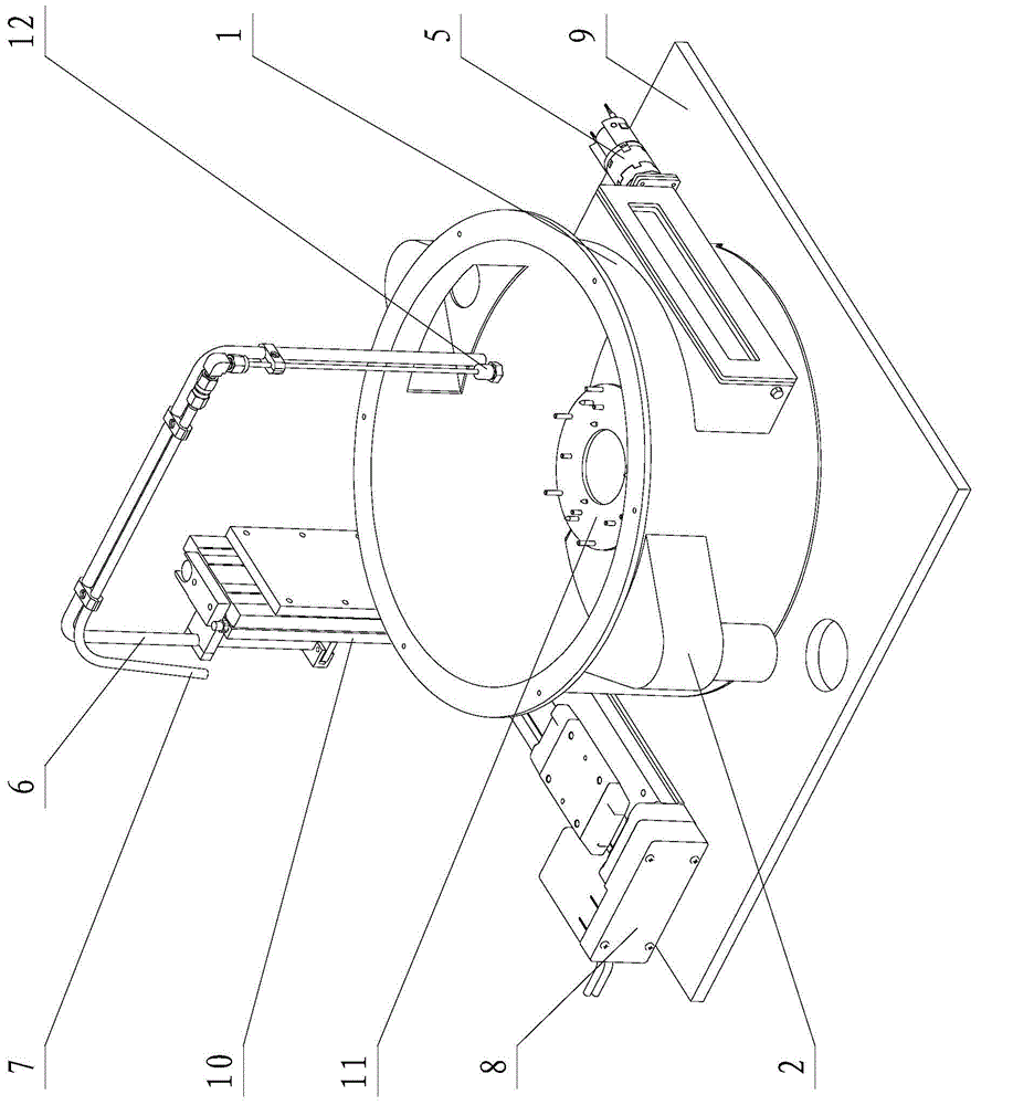
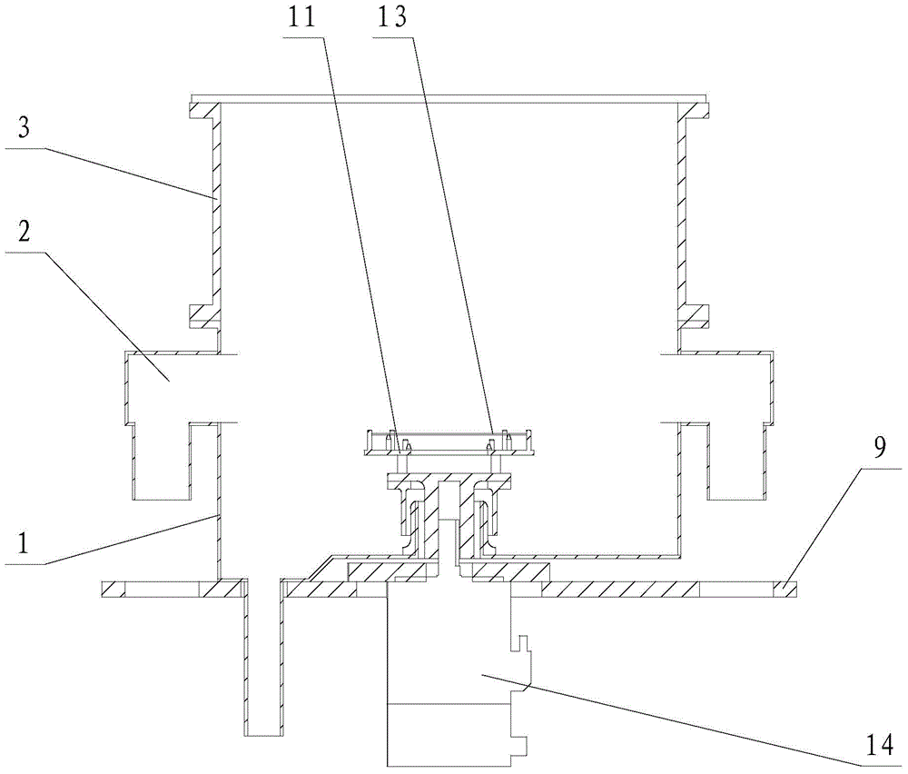
[0024] CUP (photoresist collection cup) structure of the present invention is as Figure 1~3 As shown, it includes CUP body, exhaust port 2, upper end cover 4, door opening mechanism 5, fixed support arm 6, liquid pipe 7, bottom plate 9, arm lifting mechanism 10, wafer chuck 11, nozzle 12, motor 14 and drive mechanism, wherein the CUP body is divided into detachable CUP base 1 and upper CUP3, the CUP base 1 is fixed on the bottom plate 9, the lower end of the upper CUP3 is connected with the CUP base 1 through screws, and the upper end cover 4 is installed on the upper end of the upper CUP3, The function of the upper end cover 4 is to reduce the opening size of the CUP structure, so that the exhaust air speed is higher and the wind direction is more concentrated. Both the upper CUP3 and the upper end cover 4 are made of transparent ECTFE (ethylene chlorotrif...


PUM


Abstract

The invention relates to a CUP structure preventing high-pressure water mist splashing. The CUP structure comprises a CUP body, an air discharging interface, an upper end cover, an opening mechanism, a liquid pipe, a base plate, a wafer chuck, a nozzle, a motor and a driving mechanism. The CUP body is installed on the base plate. The wafer chuck bearing a wafer is arranged inside the CUP body. The wafer chuck is driven to rotate by the motor installed on the base plate. The driving mechanism is installed on the base plate outside the CUP body. The liquid pipe is driven to move by the driving mechanism. The upper end cover is installed on the CUP body. The upper edge of the upper end cover is equipped with holes along the movement track of the liquid pipe. The liquid pipe is inserted into the CUP body through the hole and is equipped with a nozzle. A liquid supply source providing a high pressure liquid for the liquid pipe is located outside the CUP body. The high pressure liquid is sprayed on the surface of the wafer via the liquid pipe and through the nozzle. The opening mechanism and the air discharging interface are arranged on the CUP body. The CUP structure has advantages of small size, simple structure, low processing installation cost and the like, and is suitable to be used on semiconductor devices needing a high-pressure liquid function for glue removing, cleaning and the like.

Description

technical field [0001] The invention relates to a CUP structure for preventing high-pressure water mist splashing, which is suitable for semiconductor equipment using high-pressure liquids such as degumming or cleaning. Background technique [0002] In the cleaning and degumming process, high-pressure liquid is required to complete certain functions, and high-pressure liquid (usually using 5MPa~15MPa) impacts the surface of the wafer, splashing a large number of droplets and mist, and spreading to the wafer around. At present, in the equipment using high-pressure liquid, the common method is to use a completely closed process chamber, and integrate the wafer clamping mechanism, chemical supply mechanism, swing arm mechanism, etc. The control parts are well protected, and the cavity is completely sealed when using high-pressure liquid, which can not only ensure the safety of the moving structure in the cavity, but also completely control the spray and droplet splash generate...

Claims


Application Information

Patent Timeline
IPC IPC(8): H01L21/67
Inventor 张杨
Owner SHENYANG KINGSEMI CO LTD
Why Eureka
Try Eureka