
Electromagnetic circuit system and electromagnetic relay

A magnetic circuit system and electromagnetic technology, applied in the direction of electromagnetic relays, electromagnetic relay details, relays, etc., can solve the problems of ineffective use of magnetic flux, low magnetic conduction efficiency of magnetic circuits, and easy magnetic saturation, etc., to achieve assembly process Good performance, good mold punching process, and the effect of reducing the probability of magnetic saturation

Active Publication Date: 2015-11-25
XIAMEN HONGFA ELECTROACOUSTIC CO LTD
View PDF11 Cites 3 Cited by
  • Summary
  • Abstract
  • Description
  • Claims
  • Application Information

AI Technical Summary

Problems solved by technology

[0004] In the magnetic circuit structure of the prior art, on the one hand, due to the limitation of the external dimensions of the product, the magnetic circuit is prone to magnetic saturation after the coil is excited, so that the magnetic flux generated by the coil cannot be effectively utilized, and the magnetic transmission efficiency of the magnetic circuit is relatively low. low; on the other hand, the magnetic circuit system in the prior art is usually fixed by riveting the iron core and the yoke iron, resulting in the disadvantage of poor assembly process

Method used


Image

  • Electromagnetic circuit system and electromagnetic relay
  • Electromagnetic circuit system and electromagnetic relay

Examples


Embodiment 1

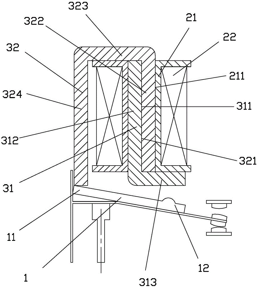
[0024] see figure 1 As shown, an electromagnetic magnetic circuit system of the present invention includes a yoke, an armature 1 and a coil; the coil is composed of a coil frame 21 and an enameled wire 22, and the coil frame 21 is provided with a through hole 211 for loading the iron core; The yoke is composed of a flat L-shaped yoke 31 and a flat U-shaped yoke 32, and one side 312 of the L-shaped yoke 31 and one side 322 of the U-shaped yoke 32 are formed by the coil frame respectively. The two ends of the through hole 211 are inserted into the through hole of the bobbin to abut against each other and constitute the iron core loaded into the through hole of the bobbin. The end edge of the other side 323 of the U-shaped yoke is used as a knife edge to support the One end 11 of the armature 1, and the other side 313 of the L-shaped yoke 31 is used as a pole surface to attract the other end 12 of the armature 1 when the coil is working.

[0025] One side 312 of the L-shaped yok...

Embodiment 2

[0035] see figure 2 As shown, an electromagnetic magnetic circuit system of the present invention is different from Embodiment 1 in that the electromagnetic magnetic circuit system is placed horizontally and is used for horizontal electromagnetic relays.

[0036] An electromagnetic relay of the present invention includes a horizontally placed electromagnetic magnetic circuit system.


PUM


Abstract

The invention discloses an electromagnetic circuit system and an electromagnetic relay. The electromagnetic circuit system comprises a yoke iron, an armature and a coil, wherein the coil is composed of a coil rack and an enameled wire, the coil rack is provided with a through hole for installing an iron core, the yoke iron comprises an L-shaped yoke iron and a U-shaped yoke iron, one edge of the L-shaped yoke iron and one side edge of the U-shaped yoke iron are respectively and oppositely inserted into the through hole of the coil rack from the two ends of the through hole of the coil rack to prop against each other so as to form the iron core installed in the through hole of the coil rack, an end edge at other side edge of the U-shaped yoke iron serves as a knife edge for supporting one end of the armature, and the other edge of the L-shaped yoke iron serves as a pole surface for attracting the other end of the armature during working of the coil. By improving the yoke iron structure, the magnetic circuit system has the characteristics of high magnetic conductivity and excellent assembly process, the usage of the enameled wire can be effectively reduced, and product volume is reduced.

Description

technical field [0001] The invention relates to an electromagnetic magnetic circuit and a relay thereof, in particular to an electromagnetic magnetic circuit system for a DC monostable state, an AC monostable state and a bistable state and an electromagnetic relay with the magnetic circuit structure. Background technique [0002] Relay is an automatic switching element with isolation function, which is widely used in communication, automobile, automatic control, household appliances and other fields, and is one of the most important control elements. [0003] Relays are divided into monostable, bistable, AC, and DC. Different application fields have different requirements for relays with different functions. The bistable relay can keep the relay in the closed or open state without additional power consumption; the AC relay can meet the requirements of the application fields that require AC input. With the rapid development of home furnishing and industrial control, the use ...

Claims


Application Information

Patent Timeline
Patent Type & Authority Applications(China)
IPC IPC(8): H01H50/16
CPCH01H50/16
Inventor 利奥波德·马特克里斯汀·怀特林景煌
Owner XIAMEN HONGFA ELECTROACOUSTIC CO LTD
Learn More