Electrochemical polishing liquid supply device

A polishing liquid and electrochemical technology, applied in the field of electrochemical polishing, can solve problems such as the increase of copper ion concentration, and achieve the effect of ensuring polishing uniformity

Active Publication Date: 2018-11-06
ACM RES SHANGHAI
View PDF8 Cites 1 Cited by
  • Summary
  • Abstract
  • Description
  • Claims
  • Application Information

AI Technical Summary

Problems solved by technology

However, after the polishing liquid sprayed onto the wafer surface flows back into the polishing liquid tank, the concentration of copper ions in the polishing liquid tank will increase.

Method used


Image

  • Electrochemical polishing liquid supply device

Examples


Embodiment Construction

[0015] In order to describe the technical content, structural features, achieved goals and effects of the present invention in detail, the following will be described in detail in conjunction with the embodiments and accompanying drawings.

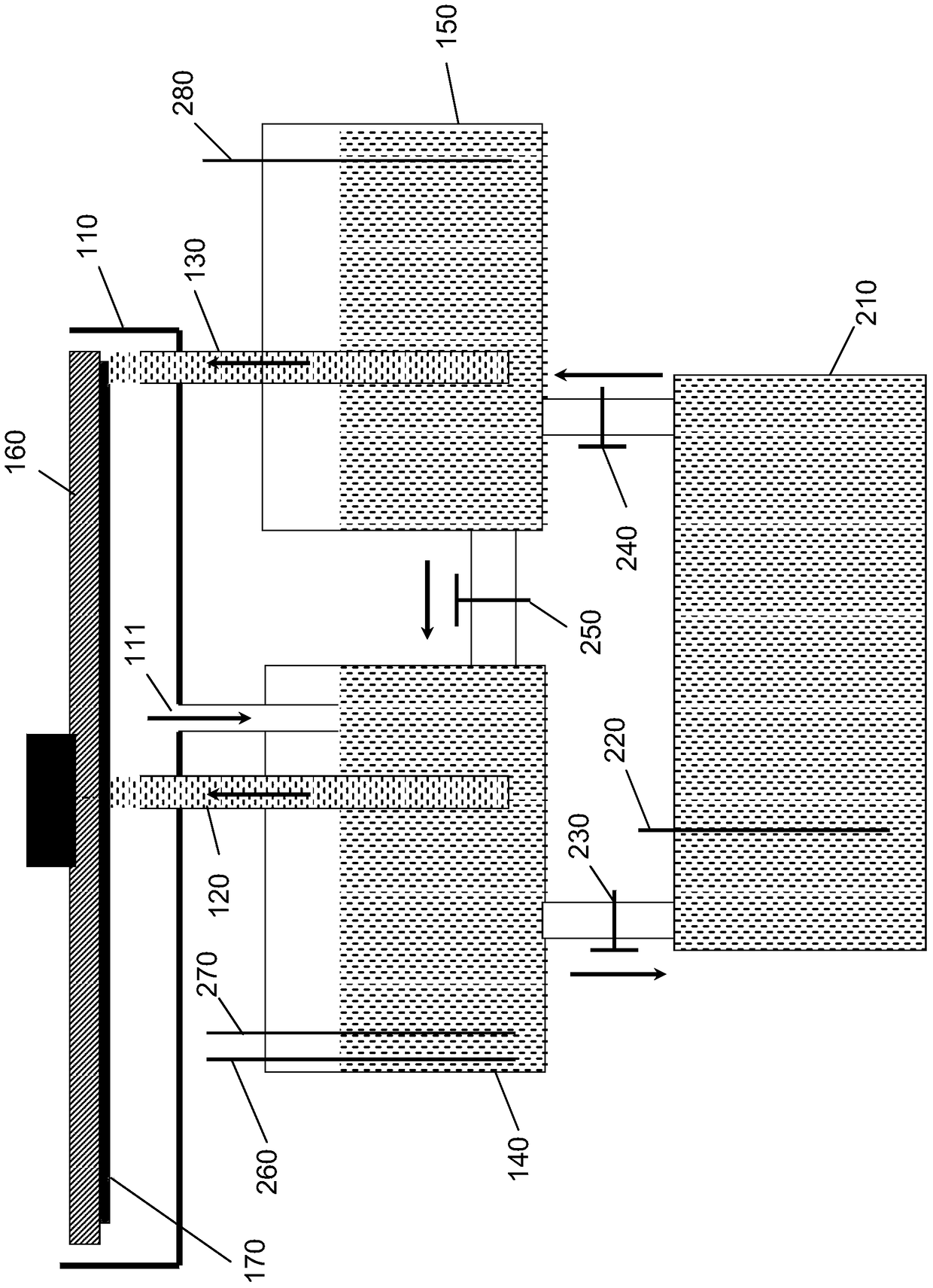
[0016] refer to figure 1 As shown, a schematic structural diagram of a liquid supply device for electrochemical polishing according to a preferred embodiment of the present invention is disclosed. The electrochemical polishing liquid supply device includes a chamber 110 , a first spray head 120 , a second spray head 130 , a first polishing liquid tank 140 and a second polishing liquid tank 150 .

[0017] The bottom wall of the chamber 110 is provided with a drain port 111 connected to the first polishing liquid tank 140 , and the polishing liquid in the chamber 110 is discharged to the first polishing liquid tank 140 through the liquid drain port 111 . The first polishing liquid tank 140 and the second polishing liquid tank 150 contain po...


PUM


Abstract

The invention discloses an electrochemical polishing liquid supply device. The device comprises a cavity, a first polishing liquid tank, a second polishing liquid tank, a first nozzle, a second nozzle, and a power supply, wherein the cavity is provided with a liquid discharge opening. The first polishing liquid tank is filled with polishing liquid, and is connected to the liquid discharge opening of the cavity. The second polishing liquid tank is filled with polishing liquid. The upper opening of the first nozzle is arranged in the cavity, the lower opening of the first nozzle is arranged in the first polishing liquid tank, and the first nozzle can spray the polishing liquid in the first polishing liquid tank onto the surface of a wafer to be polished through the upper opening. The upper opening of the second nozzle is arranged in the cavity, the lower opening of the second nozzle is arranged in the second polishing liquid tank, and the second nozzle can spray the polishing liquid in the second polishing liquid tank onto the external rim of the wafer to be polished through the upper opening. The negative pole of the power supply is electrically connected to the first nozzle, and the positive pole of the power supply is electrically connected to the second nozzle.

Description

technical field [0001] The invention relates to the technical field of electrochemical polishing, in particular to a liquid supply device for electrochemical polishing. Background technique [0002] In the integrated circuit manufacturing process, chemical mechanical polishing (CMP) technology has been widely used in the interlayer global planarization of single crystal silicon substrates and multilayer metal interconnection structures. Chemical mechanical polishing can polish and planarize the metal layer formed on the non-recessed areas of the dielectric material. Although chemical mechanical polishing can only polish the metal layer without affecting the dielectric layer, however, due to its strong mechanical force, chemical mechanical polishing will have some harmful effects on the structure of integrated circuits, especially with very large scale integrated circuits and With the rapid development of ultra-large-scale integrated circuits, copper and low-K or ultra-low-K...

Claims


Application Information

Patent Timeline
Patent Type & Authority Patents(China)
IPC IPC(8): C25F7/00C25F7/02C25F3/22
Inventor 代迎伟金一诺王坚王晖
Owner ACM RES SHANGHAI
Why Eureka
Try Eureka