Rotational atherectomy device with biasing clutch

A kind of atheromatous plaque, clutch technology, applied in the direction of surgery, surgical cutting instruments, medical science, etc., can solve the problem of injuring patients or devices

Inactive Publication Date: 2015-11-18
CARDIOVASCULAR SYST INC
View PDF12 Cites 1 Cited by
  • Summary
  • Abstract
  • Description
  • Claims
  • Application Information

AI Technical Summary

Problems solved by technology

This sudden release of energy may result in injury to the patient or device and should be avoided

Method used


Image

  • Rotational atherectomy device with biasing clutch
  • Rotational atherectomy device with biasing clutch
  • Rotational atherectomy device with biasing clutch

Examples


Embodiment Construction

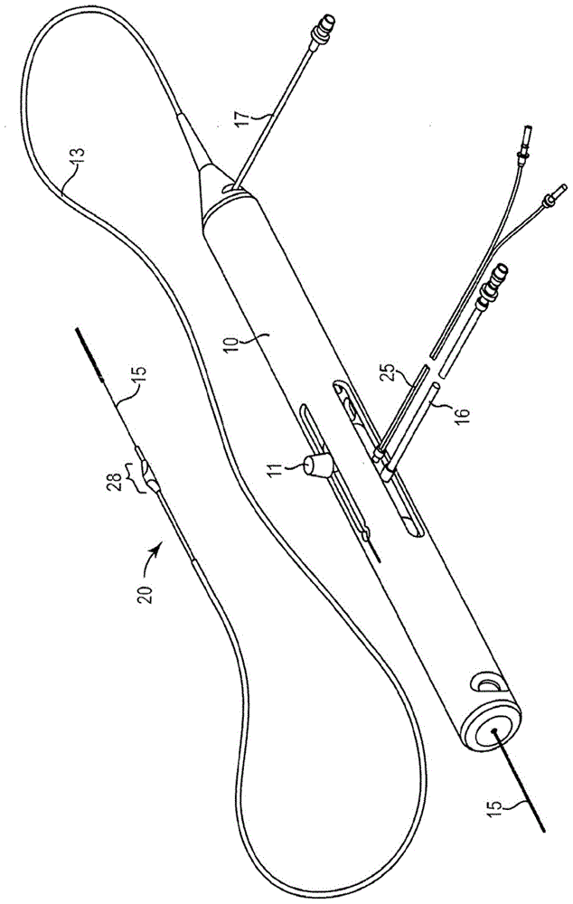
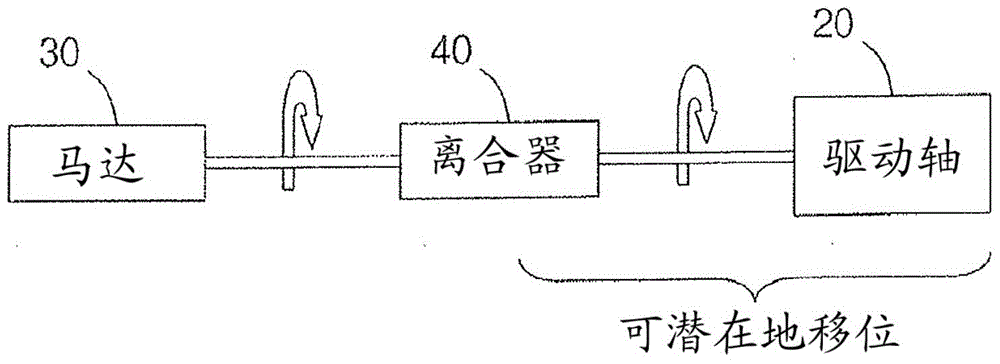
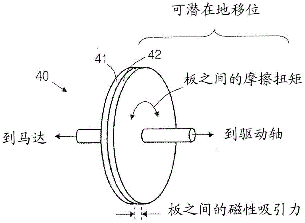
[0045] An atherectomy device having a clutch between a motor and a drive shaft is disclosed. Clutches may include two plates that rely on friction to transfer torque from one plate to the other. The clutch may have a magnetic normal attraction holding the plates together, or, in another embodiment, a biasing mechanism may hold the plates together. For relatively low torques, the stiction torque holds the plates together, and the plates rotate together without slipping, as is the case during normal use. For relatively high torques, as occurs when the distal end of the drive shaft encounters an obstacle and comes to a sudden stop, the high torque exceeds the maximum possible static friction torque, and the plates slip. When sliding, the plates transmit kinetic friction torque low enough to avoid damage to the patient or the atherectomy device. In some cases, the torque levels associated with stopping of the distal end of the drive shaft are selected to mimic those of known ath...


PUM


Abstract

A rotational atherectomy system may include a drive shaft, a motor, and a clutch with a threshold torque where the clutch may include a motor plate rotationally connected to the motor, a drive shaft plate rotationally connected to the drive shaft, and a biasing clutch configured to rotationally engage the motor plate and the drive shaft plate, wherein torques less than the threshold torque are transmitted completely between the motor plate and the drive shaft plate, which remain rotationally coupled by static friction, and wherein torques greater than the threshold torque cause the motor plate and the drive shaft plate to rotate relative to one another and cause a residual torque to be transmitted between the motor and the drive shaft, the residual torque being less than the threshold torque and being determined by a kinetic coefficient of friction.

Description

[0001] inventor [0002] Joseph Higgins, a citizen of the United States of America, residing in Minnetonka, Minnesota [0003] Jeffrey Allen McBroom, a citizen of the United States of America, residing in Champlin, Minnesota [0004] Cross References to Related Applications [0005] This application claims priority to U.S. Provisional Patent Application 61 / 787,027, filed March 15, 2013, entitled "Rotary Atherectomy Device With Biasing Clutch," which claims The contents are hereby incorporated by reference in their entirety. [0006] Statement Regarding Federally Sponsored Research or Development [0007] Not applicable technical field [0008] The present invention relates to devices and methods for removing tissue from a bodily passage (eg, removing atherosclerotic plaque from an artery) using a rotational atherectomy device. In particular, the present invention relates to improvements in rotary atherectomy devices having biased clutches and / or shock absorbing elements. ...

Claims


Application Information

Patent Timeline
Patent Type & Authority Applications(China)
IPC IPC(8): A61B17/22
CPCA61B17/320758A61B2019/301A61B2090/031
Inventor 约瑟夫·希金斯杰弗里·艾伦·麦克布鲁姆
Owner CARDIOVASCULAR SYST INC
Why Eureka
Try Eureka