
Step-by-step analysis and prediction method for dynamic performances of rubber material structure

A rubber material and dynamic performance technology, applied in the fields of instruments, computing, electrical digital data processing, etc., can solve the problems of complex superposition process, certain difficulty, and few practical applications

Active Publication Date: 2015-11-18
SHANDONG UNIV
View PDF1 Cites 22 Cited by
  • Summary
  • Abstract
  • Description
  • Claims
  • Application Information

AI Technical Summary

Problems solved by technology

However, the finite element analysis process requires a complete simulation of the actual loading process of the rubber material structure before it is possible to obtain results that meet the engineering precision requirements. Therefore, it is difficult to meet the actual needs by using the above-mentioned single material model.
Some methods establish a more complex nonlinear constitutive model that can describe the properties of more than two rubber materials at the same time, but such material models are usually not built into commonly used finite element software, and require secondary development before they can be used. However, some methods use composite material models to model rubber material structures, but such models need to construct multiple constitutive models such as hyperelasticity, viscoelasticity, and elastoplasticity at the same time. It is also necessary to superimpose the calculation results, and the acquisition of material parameters and the superposition process of the results are relatively complicated and difficult, and there are few practical applications

Method used


Image

  • Step-by-step analysis and prediction method for dynamic performances of rubber material structure
  • Step-by-step analysis and prediction method for dynamic performances of rubber material structure
  • Step-by-step analysis and prediction method for dynamic performances of rubber material structure

Examples


Embodiment Construction

[0054] The specific implementation process of the present invention will be described in detail below with reference to the accompanying drawings.

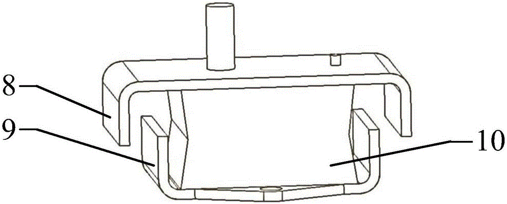
[0055] right as figure 2 The dynamic performance of a rubber isolator shown is analyzed and predicted and compared with experimental test results. The metal upper and lower frames of the rubber vibration isolator are respectively bonded with the rubber material cushion through vulcanization. The present invention includes the following test prediction steps:

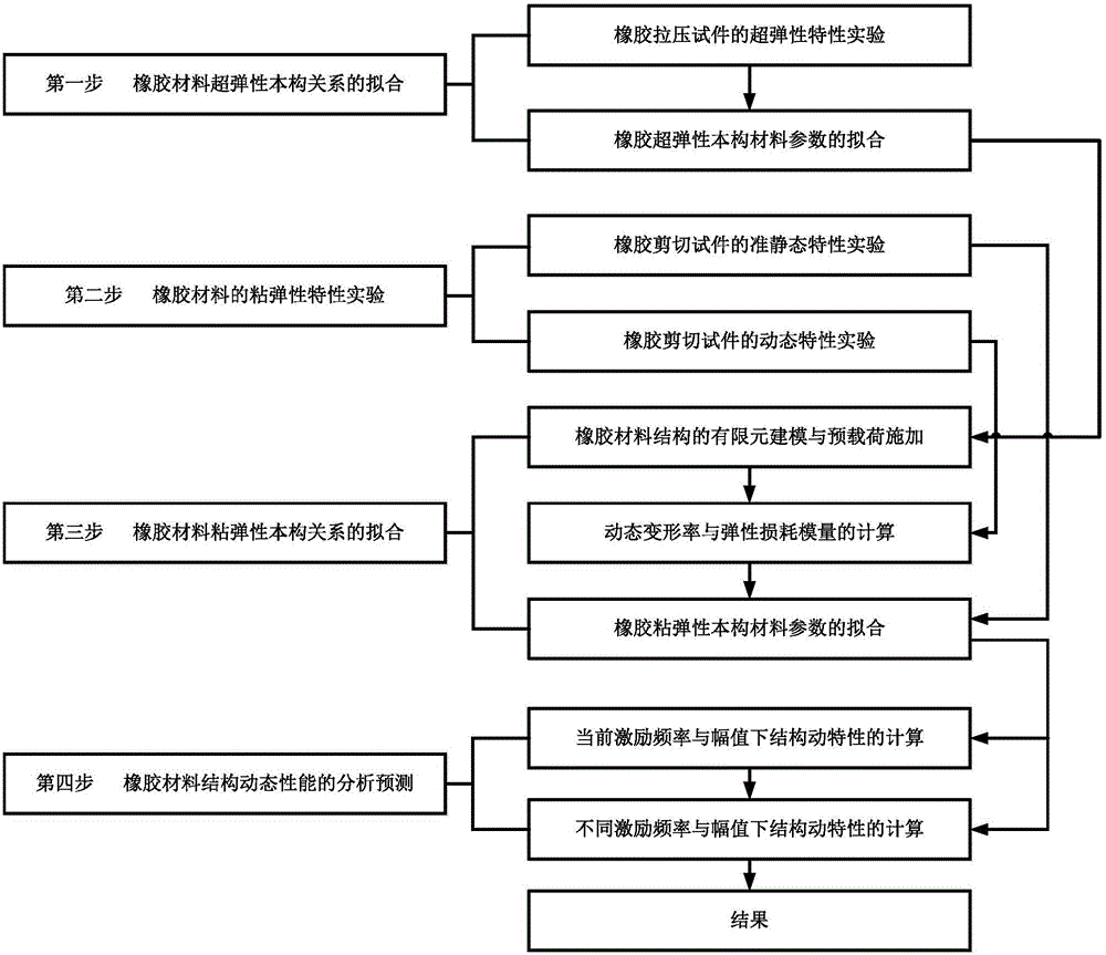
[0056] The first step is the fitting of the hyperelastic constitutive relation of the rubber material

[0057] (1) First, obtain the hyperelastic stress-strain relationship of the rubber material through the quasi-static elastic characteristic test of the rubber tensile and compression specimen: using the same batch of rubber material as the target rubber material structure, prepare such as image 3 Cylindrical test block shown; as Figure 4 Dumbbell-shaped test piece s...


PUM


Abstract

The present invention relates to an analysis and prediction method for dynamic performances of a rubber material structure, and particularly to a step-by-step analysis and prediction method for the dynamic performances of the rubber material structure. The step-by-step analysis and prediction method is used for performing finite element analysis and prediction of the high-frequency dynamic performances on the rubber material structure. The method comprises the following test and prediction steps: step one, fitting a super-elastic constitutive relation of the rubber material; step two, performing a viscoelasticity property test on the rubber material under different strain amplitudes; step three, fitting a viscosity constitutive relation of the rubber material; and step four, analyzing and predicating the dynamic performances of the rubber material structure. A calculation result is a final result, without the need of superposition of the calculation result, thereby reducing the computational difficulty and shortening the solution time; and an actual modeling and analysis process is more simple, clear, and easy to understand and operate, and has higher prediction accuracy, so as to meet the requirements of engineering analysis.

Description

1. Technical field [0001] The invention relates to a method for analyzing and predicting structural dynamic properties of rubber materials, in particular to a step-by-step analysis and predicting method for structural dynamic properties of rubber materials. 2. Background technology [0002] With the rapid advancement of the national economy and modern industry, machinery and equipment are gradually developing in the direction of large-scale, high-speed and complex, resulting in increasingly prominent vibration and noise hazards, so it is necessary to take more effective measures to control the mechanical equipment. vibration and noise levels. The rubber material structure can effectively attenuate the vibration of the vibration source or isolate the transmission of vibration, and is one of the components widely used in the field of vibration isolation and vibration reduction. Since the elastic modulus of the rubber material is much smaller than that of the metal, and at the...

Claims


Application Information

Patent Timeline
Patent Type & Authority Applications(China)
IPC IPC(8): G06F17/50
Inventor 王亚楠刘玥
Owner SHANDONG UNIV
Learn More