
Intelligent magnetic sensor and vehicle detection method based on same

A magnetic sensor and intelligent technology, applied in instruments, measuring devices, measuring magnetic variables, etc., can solve the problems of short detection distance, small peak duration, low power, etc., and achieve strong impact resistance, good applicability, and reduced power consumption. consumption effect

Inactive Publication Date: 2015-11-18
袁丽
View PDF9 Cites 8 Cited by
  • Summary
  • Abstract
  • Description
  • Claims
  • Application Information

AI Technical Summary

Problems solved by technology

[0006] A micro-magnetic sensor is disclosed in CN200810181901X, which uses the magnetoresistance effect of amorphous wire and the principle of electromagnetic relationship to convert magnetic field information into electrical signals for measurement, but the sensor works together through the bias current and excitation current of sub-sensitive devices, The bias current can generate higher temperature drift and affect the detection results.
[0007] CN201110055819 discloses a traffic information detection system, wherein the thumbtack structure sensor uses the impedance change of the magnetic sensitive material-amorphous wire to detect the change of the disturbed geomagnetic field when the vehicle passes by, and the dynamic parameters adopt the form of pulse power supply, resulting in The problem is that the power consumption is large, the power is small, and the parameter acquisition in the form of pulse power supply is not accurate during the implementation process. Because the peak duration is small, and there is a time difference when the device is started, the peak value cannot be accurately collected, and the detection The distance is short, which requires a large number of sensors and costs a lot of money

Method used


Image

  • Intelligent magnetic sensor and vehicle detection method based on same
  • Intelligent magnetic sensor and vehicle detection method based on same
  • Intelligent magnetic sensor and vehicle detection method based on same

Examples


Embodiment 1

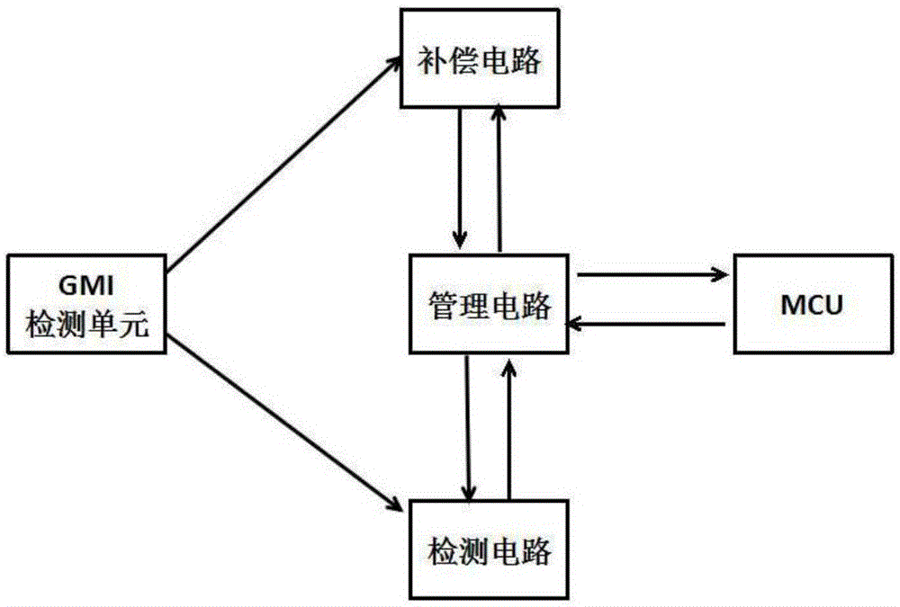
[0062] Such as figure 1 It is the circuit block diagram of the intelligent magnetic sensor of the present invention, in this specific embodiment, as figure 1 As shown, the present invention provides a kind of intelligent magnetic sensor, and described magnetic sensor comprises MCU circuit, GMI detection unit, compensation circuit, detection circuit and management circuit; Described GMI detection unit is connected with described compensation circuit, detection circuit, so The management circuit is respectively connected to the compensation circuit, the detection circuit, and the MCU circuit; wherein, the GMI detection unit is used to detect a magnetic signal; the compensation circuit is used to perform magnetic compensation on the magnetic signal detected by the GMI detection unit; The detection circuit is used to detect the environmental magnetic field where the GMI detection unit is located; the management circuit is used to amplify the magnetic signal detected by the GMI det...

Embodiment 2

[0075] The present invention also provides a magnetic sensor probe, the probe includes an amorphous wire pad, a conductor pad, a wire, an amorphous wire, a winding shaft and a skeleton; the middle section of the skeleton is set as a winding shaft, and the two ends of the skeleton are A terminal is provided, and the cross-sectional area of ​​the winding shaft is smaller than the cross-sectional area of ​​the terminal; the amorphous wire is embedded in the center of the skeleton, and the amorphous wire is placed concentrically with the winding shaft; two non-crystalline wires are arranged on the skeleton. Crystal wire pads, 4 conductor pads.

[0076] Such as Figure 9 As shown, it is the shape and parameter setting of the skeleton in a specific implementation of this embodiment. The skeleton can be made into a dumbbell shape, and the middle is set as a winding shaft for winding wire coils. Figure 9 The dimensions in are used only as an exemplary preferred embodiment, and are n...

Embodiment 3

[0085] In a specific embodiment, on the basis of the above-mentioned embodiments, the present invention also provides a vehicle detector using the above-mentioned smart magnetic sensor, such as Figure 13 Shown, described vehicle detector comprises intelligent magnetic sensor, system microprocessor (MCU), wireless transmitter module, wireless RFID card reader module; Described intelligent magnetic sensor is used for monitoring the vehicle disturbed earth field magnetic anomaly signal of parking space , the system microprocessor is used to perform analog-to-digital conversion, acquisition, and signal processing and analysis on the detected signal of the presence or absence of a vehicle in a parking space and the magnetic anomaly signal of the vehicle disturbance geomagnetic field, so as to obtain the vehicle information of the parking space, and convert the parking space The information is sent through the wireless transmitting module; the RFID card reader module is used to read...


PUM


Abstract

The invention provides an intelligent magnetic sensor comprises a housing, a power supply module, a communication module, a magnetic circuit module, and a circuit module. The magnetic circuit module comprises a signal induction unit. The circuit module comprises a signal acquisition unit and a signal processing unit which are formed by GMI chip matching processing units. The housing is in a box shape. The power supply module, the signal induction unit, and the signal acquisition unit are located in the housing. The signal induction unit generates an analog signal by sensing a geomagnetic field. The signal acquisition unit receives the analog signal and transmits the analog signal to the signal processing unit. The signal processing unit processes and computes the received analog signal, converts the analog signal into a digital signal, and transmits the digital signal to the communication module. The intelligent magnetic sensor is simple in structure, accurate in detection, low in power consumption, low in cost, intelligent and miniaturized.

Description

technical field [0001] The invention relates to the technical field of weak magnetic field measurement, in particular to an intelligent magnetic sensor, a probe used for the intelligent magnetic sensor, and a vehicle detection method based on the intelligent magnetic sensor. Background technique [0002] The invention belongs to the technical field of weak magnetic field measurement. The invention relates to an intelligent weak magnetic field detection sensor and a slowly changing and transient magnetic field detection method, in particular to a giant magneto-impedance amorphous wire sensor and an amorphous wire-based The giant magnetic magneto-impedance effect can be used in magnetic sensors in the fields of vehicle detection, stress detection of ferromagnetic engineering structures, and broken wire detection of steel strands. [0003] At this stage, new sensors are gradually developing in the direction of miniaturization, digitization, intelligence, multi-function, systema...

Claims


Application Information

Patent Timeline
Patent Type & Authority Applications(China)
IPC IPC(8): G01R33/09
CPCG01R33/09
Inventor 袁丽
Owner 袁丽
Learn More