Pipeline for drying machine

A dryer and pipeline technology, applied in dryers, drying gas layout, drying and other directions, can solve the problems of hot air not being delivered, uneven drying, etc.

Inactive Publication Date: 2015-11-18
JIANGYIN DRY EQUIP MFR
View PDF0 Cites 0 Cited by
  • Summary
  • Abstract
  • Description
  • Claims
  • Application Information

AI Technical Summary

Problems solved by technology

[0002] Ordinary dryer pipes use through holes or grooves to blow the hot air, but there will be many blank areas in the middle, and the hot air cannot be sent, resulting in uneven drying

Method used


Image

  • Pipeline for drying machine

Examples


Embodiment Construction

[0008] All features disclosed in this specification, or steps in all methods or processes disclosed, may be combined in any manner, except for mutually exclusive features and / or steps.

[0009] Any feature disclosed in this specification (including any appended claims, abstract and drawings), unless expressly stated otherwise, may be replaced by alternative features which are equivalent or serve a similar purpose. That is, unless expressly stated otherwise, each feature is one example only of a series of equivalent or similar features.

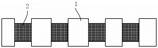
[0010] As shown in Figure 1, a pipeline for a dryer includes a connecting pipe 1, and a heating wire is arranged inside the connecting pipe 1, and a plurality of connecting pipes 1 are arranged in sequence, and the adjacent connecting pipes 1 are connected through a mesh pipe. 2 are connected to each other to form a pipeline, and one end of the pipeline is closed, and the bundled wires are placed on the mesh tube 2, and the hot air is blown to...


PUM


Abstract

The invention discloses a pipeline for a drying machine. Bundles of wires are placed on meshy pipes, hot air is scattered to the surfaces of the wires from the meshy pipes, the contact area between the hot air and the wires is larger, and thus the wires are dried more quickly and more uniformly.

Description

technical field [0001] The invention relates to a pipe for a dryer. Background technique [0002] Ordinary dryer pipes use through holes or grooves to disperse the hot air, but there will be many blank areas in the middle, and the hot air cannot be sent, resulting in uneven drying. Contents of the invention [0003] The invention relates to a pipeline for a dryer, which can make hot air blowing more uniform. [0004] To achieve this goal, the structure adopted in the present invention is: a pipeline for a dryer, including a connecting pipe, a plurality of connecting pipes are arranged in sequence, and adjacent connecting pipes are connected to each other through a mesh pipe, and the mesh pipe The diameter of the pipe is smaller than that of the connecting pipe, and the connecting pipe is provided with a heating wire. [0005] The beneficial effect is: the bundled wires are placed on the mesh tube, the hot air is scattered from the mesh tube to the surface of the wires, t...

Claims


Application Information

Patent Timeline
IPC IPC(8): F26B21/00
Inventor 许金峰
Owner JIANGYIN DRY EQUIP MFR
Why Eureka
Try Eureka