
Bridge deck structure composed of prefabricated UHPC (Ultra High Performance Concrete) slabs and steel bridge deck and construction method thereof

A steel bridge deck and bridge deck technology, applied in bridges, bridge parts, bridge construction, etc., can solve problems such as easy shrinkage and cracking of ultra-high performance concrete, difficult maintenance of cast-in-place concrete, and shortened bridge deck pavement life. Achieve the effect of suitable factory construction, high rigidity and good fatigue resistance

Inactive Publication Date: 2015-11-18
FUZHOU UNIVERSITY
View PDF8 Cites 23 Cited by
  • Summary
  • Abstract
  • Description
  • Claims
  • Application Information

AI Technical Summary

Problems solved by technology

This kind of composite bridge deck structure adopts integral cast-in-place construction. Because ultra-high performance concrete is easy to shrink and crack, the existing cast-in-place construction technology cannot guarantee the construction quality, and the maintenance of large-area cast-in-place concrete is very difficult, and the concrete strength will vary depending on If the maintenance is not in place, it will be greatly reduced, which will greatly reduce the life of the bridge deck pavement
If construction measures are taken to overcome the unfavorable factors caused by the overall cast-in-place construction, it will lead to a substantial increase in construction costs

Method used


Image

  • Bridge deck structure composed of prefabricated UHPC (Ultra High Performance Concrete) slabs and steel bridge deck and construction method thereof
  • Bridge deck structure composed of prefabricated UHPC (Ultra High Performance Concrete) slabs and steel bridge deck and construction method thereof
  • Bridge deck structure composed of prefabricated UHPC (Ultra High Performance Concrete) slabs and steel bridge deck and construction method thereof

Examples


Embodiment Construction

[0030] In order to make the above-mentioned features and advantages of the present invention more comprehensible, the following specific embodiments are described in detail with reference to the accompanying drawings.

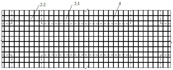
[0031] Such as Figure 2~7 As shown, a bridge deck structure composed of a prefabricated ultra-high performance concrete slab and a steel bridge deck includes a steel bridge deck 1 and an ultra-high performance concrete slab 2 covered on the steel bridge deck, and the ultra-high performance concrete slab 2 It is a prefabricated component, and the prefabricated slab 2-1 is connected into an integral ultra-high performance concrete slab 2 by the reserved cast-in-place belt 2-2, and then connected with the steel bridge deck 1 by cement-based adhesive 3 to form a composite bridge deck structure .

[0032] Wherein, the main material cement of the cement-based binder 3 can be ordinary Portland cement, sulphoaluminate cement, alkali-activated cement, magnesium cement...


PUM

PropertyMeasurementUnit
Diameteraaaaaaaaaa

Abstract

The invention relates to a bridge deck structure composed of prefabricated UHPC (Ultra High Performance Concrete) slabs and a steel bridge deck and a construction method thereof. The bridge deck structure comprises the steel bridge deck and the UHPC slabs covering the steel bridge deck, wherein the UHPC slabs are arranged at intervals, UHPC cast-in-situ belts are arranged between adjacent UHPC slabs, and the bottoms of the UHPC slabs are connected with the steel bridge deck through cement based adhesives so as to form the composite bridge deck structure. Shear connectors can be appropriately arranged in the cast-in-situ belts so as to enhance the connecting effect of the prefabricated slabs and the steel bridge deck. The construction method of the structure comprises the following steps: constructing steel beams and the steel bridge deck; manufacturing and installing the UHPC slabs; constructing the UHPC cast-in-situ belts; and constructing the surface of the bridge deck. The structure is reasonable in stress, high in strength and stiffness, capable of effectively avoiding the generation of steel bridge deck defects, simple, capable of reducing relatively large shrinkage in a cast-in-situ process of UHPC, and easy to realize batch production in factories; and the structure has important practical values and favorable economic benefits.

Description

technical field [0001] The invention relates to the technical field of bridge deck structures, in particular to a bridge deck structure and construction method composed of prefabricated ultra-high performance concrete slabs and steel deck decks. Background technique [0002] The bridge deck structure of highway steel bridge is mainly composed of bridge deck and bridge deck pavement, which is the main structure that directly bears the wheel load on the bridge and transmits it to the main girder, and is also one of the most vulnerable parts of the bridge structure. It is mainly manifested in the cracking of the steel bridge deck and the vulnerable damage of the bridge deck pavement. Although people in the bridge and road circles at home and abroad have done a lot of theoretical and experimental research on steel bridge decks and steel bridge deck pavements, they have tried to improve the material properties of pavement mixtures, optimize the thickness of pavement layers, and i...

Claims


Application Information

Patent Timeline
IPC IPC(8): E01D19/12
Inventor 赵秋陈宝春吴怀中陈平
Owner FUZHOU UNIVERSITY
Learn More