Permanent magnetic separation column suitable for strongly or weakly magnetic minerals

A technology of weak magnetic and magnetic separation columns, applied in the field of magnetic separation columns, can solve the problems of large tailing, many electrical failures, large water consumption, etc., and achieve the effect of improving the concentrate grade, large equipment capacity and simple structure

Inactive Publication Date: 2015-11-18
唐竹胜
View PDF9 Cites 6 Cited by
  • Summary
  • Abstract
  • Description
  • Claims
  • Application Information

AI Technical Summary

Problems solved by technology

[0003] However, most of the magnetic separation columns on the market are electromagnetic magnetic separation columns, which have disadvantages such as weak magnetic field strength, poor magnetic agglomeration and separation, more electrical failures, unstable operation, large water consumption, and large tailing. For iron ore and other strong magnetic minerals, the grade of the concentrate is limited, and it is not suitable for the selection of weak magnetic refractory iron ores such as hematite, limonite, and siderite.
[0004] Due to the problems of many electrical failures and unstable operation in the electromagnetic magnetic separation column, a permanent magnetic magnetic separation column appeared, but the existing permanent magnetic magnetic separation column device has complex structure, poor magnetic agglomeration and separation, Defects such as large water consumption, large tailing volume, and low production capacity of a single device

Method used


Image

  • Permanent magnetic separation column suitable for strongly or weakly magnetic minerals
  • Permanent magnetic separation column suitable for strongly or weakly magnetic minerals
  • Permanent magnetic separation column suitable for strongly or weakly magnetic minerals

Examples


Embodiment 1

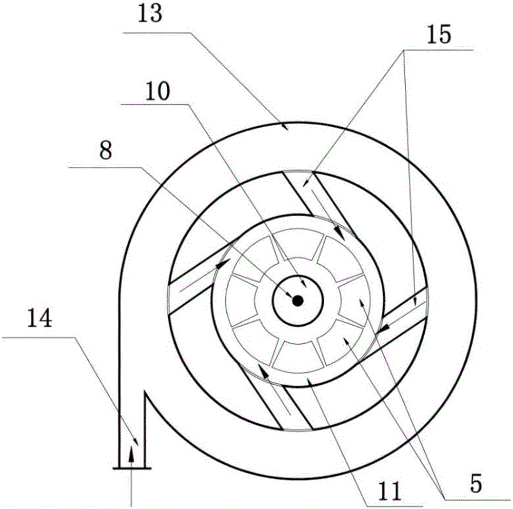
[0023] A permanent magnet magnetic separation column suitable for strong magnetic minerals or weak magnetic minerals, including a cylinder 1 with an open top, an overflow box 2 installed on the top of the cylinder 1, and a concentrate installed at the bottom of the cylinder 1 The bucket 3 is special in that the top of the cylinder 1 passes through the middle of the bottom wall of the overflow tank 2, and the bottom wall of the overflow tank 2 is provided with a tailings outlet 4, and the cylinder 1 The bottom wall of 1 is provided with a concentrate leakage hole 5 for communicating with the concentrate hopper 3, and the bottom of the concentrate hopper 3 is provided with a concentrate outlet 6, and an impeller feeder is installed on the concentrate outlet 6 7. The cylinder body 1 is fixedly installed with a central rotating shaft 8 extending along the central axis direction, and the top end of the central rotating shaft 8 is fixed on the top wall of the overflow box 2, on the o...

Embodiment 2

[0026] A permanent magnet magnetic separation column suitable for strong magnetic minerals or weak magnetic minerals, including a cylinder 1 with an open top, an overflow box 2 installed on the top of the cylinder 1, and a concentrate installed at the bottom of the cylinder 1 The bucket 3 is special in that the top of the cylinder 1 passes through the middle of the bottom wall of the overflow tank 2, and the bottom wall of the overflow tank 2 is provided with a tailings outlet 4, and the cylinder 1 The bottom wall of 1 is provided with a concentrate leakage hole 5 for communicating with the concentrate hopper 3, and the bottom of the concentrate hopper 3 is provided with a concentrate outlet 6, and an impeller feeder is installed on the concentrate outlet 6 7. The cylinder body 1 is fixedly installed with a central rotating shaft 8 extending along the central axis direction, and the top end of the central rotating shaft 8 is fixed on the top wall of the overflow box 2, on the o...


PUM


Abstract

The invention belongs to the field of magnetic separation columns and particularly relates to a permanent magnetic separation column suitable for strongly or weakly magnetic minerals. Permanent magnetic systems are adopted, the magnetic field intensity can be adjusted within 1,600-16,000 Gs, and an inner permanent magnetic field mechanism and an outer permanent magnetic field mechanism which are in spiral distribution and movement are arranged simultaneously meet the requirement for production of big or small magnetic separation columns; fed water and minerals in a mineral separation chamber conduct inversely spiral upward movements to separate concentrate from tailing more radically, so that the concentrate grade is further improved; concentrate particles conduct obliquely downward slow movement under dual actions of the magnetic field and the dead weight, so that the tailing missing amount is reduced; and the permanent magnetic separation column is simple in structure, stable and reliable, low in water consumption, high in equipment output, and is simultaneously suitable for separation of such strongly-magnetic minerals as magnetite and such weakly-magnetic minerals as hematite, limonite and siderite.

Description

technical field [0001] The invention belongs to the field of magnetic separation columns, and in particular relates to a permanent magnetic separation column suitable for strong magnetic minerals or weak magnetic minerals. Background technique [0002] my country is a country rich in low-poverty and refractory iron ore resources. Low-poverty and refractory iron ore accounts for more than 97% of iron ore resources, and most of them are weak magnetic refractory ores. In recent years, the resources of easy-to-separate iron ore have become less and less. Therefore, people have higher and higher requirements for high-performance enrichment and beneficiation equipment for weakly magnetic and difficult-to-separate iron ore. In order to further reduce the gangue content in the enriched iron ore powder, magnetic separation column beneficiation equipment has appeared on the market. [0003] However, most of the magnetic separation columns on the market are electromagnetic magnetic se...

Claims


Application Information

Patent Timeline
IPC IPC(8): B03C1/32
Inventor 唐竹胜唐佳
Owner 唐竹胜
Why Eureka
Try Eureka