Portable emergency communication instruction receiving display terminal

An emergency communication and command receiving technology, applied in the field of emergency communication, can solve problems such as power, transportation, energy infrastructure damage, loss of external communication functions, and equipment placement space limitations, and meet the needs of high portability and environmental adaptability, ensuring Detachability and independence, the effect of strong adaptability to conditions

Active Publication Date: 2015-11-11
ANHUI SUN CREATE ELECTRONICS
View PDF6 Cites 1 Cited by
  • Summary
  • Abstract
  • Description
  • Claims
  • Application Information

AI Technical Summary

Problems solved by technology

However, since the scene of an emergency may be located in a deep mountain or in an area of ​​electromagnetic interference, the short-wave receiving equipment of individual soldiers often causes poor reception or even failure to receive, which seriously affects the work efficiency of on-site personnel
In addition, it relies heavily on the large-scale equipment display terminal on site as the individual communication tool at the forwarding end. Once the large-scale equipment display terminal fails to work due to damage, etc., the relevant personnel as subordinates will completely lose the external communication function, until the personal safety of the corresponding personnel is endangered.
More importantly, due to the complexity of the environment of the emergency treatment site, the power, transportation, energy and other infrastructure at the event site may be damaged. At the same time, there will be many restrictions on the space for equipment placement. In many cases, it is even impossible to realize the above-mentioned large-scale The erection and normal use of equipment are very unfavorable for the rapid development of emergency work such as disaster relief and rescue.

Method used


Image

  • Portable emergency communication instruction receiving display terminal
  • Portable emergency communication instruction receiving display terminal
  • Portable emergency communication instruction receiving display terminal

Examples


Embodiment Construction

[0029] For ease of understanding, the specific implementation structure and workflow of the present invention are described below in conjunction with the accompanying drawings:

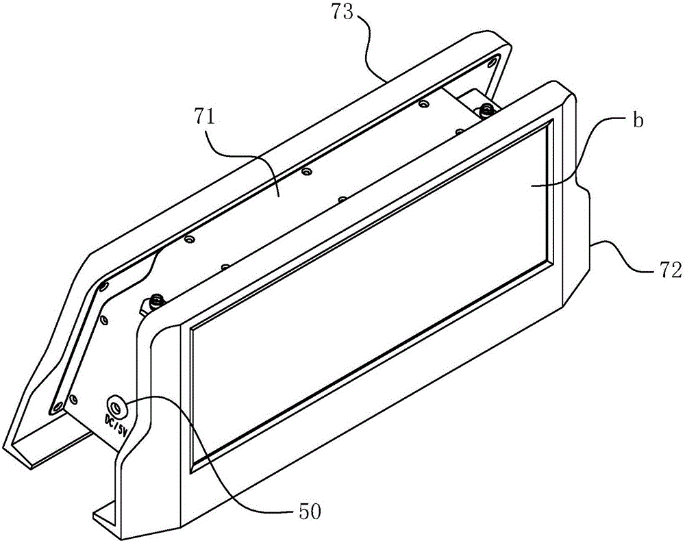
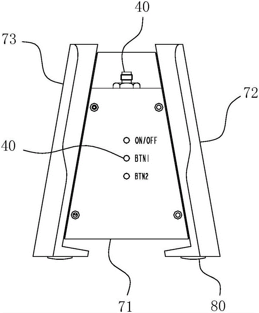
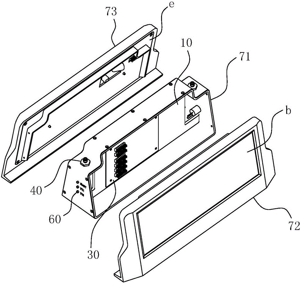
[0030] Concrete structure of the present invention, as Figure 1-6As shown, it includes a front cover 72 , a rear cover 73 and an intermediate housing 71 . The middle housing 71 is in a cylindrical structure, and is divided into two independent chambers, front and rear, by the diaphragm 10 . The front cover plate 72 and the rear cover plate 73 play a sealing and covering role for two identical cavities. A transparent PC protective panel b, an LED display screen d, a screen PCBc, and a liner e that compresses the above-mentioned components are arranged on the cover body frame a constituting each cover plate. The two groups of LED display screens d on the two cover plates work independently without interfering with each other, and are detachably connected to the power supply PCB30 and the signal recei...


PUM


Abstract

The invention belongs to the field of emergency communications, and in particular relates to a portable emergency communication instruction receiving display terminal. The terminal comprises an outer shell in which a diaphragm plate is arranged; a signal receiving processing PCB and a power source PCB are solid connected with two surfaces of the diaphragm plate in a clinging type, and the diaphragm plate is at least made of aluminum alloy convenient for radiating; the outer wall of the outer shell is provided with an antenna switching coaxial connector, a DC power source interface and a key PCB; the outer wall of the outer shell is further provided with a display screen component, the display screen component is respectively connected with the signal receiving processing PCB and the power source PCB to construct electric connection matching in winding displacement. Through the adoption of the terminal disclosed by the invention, the instruction receiving terminal in the emergency communication is independent in core function, extremely high in portability and environment suitability. The single pawn portability is strong, each carrier can form an independent point-to-point signal receiving terminal system by self, the site strain efficiency in the emergency event can be obviously promoted.

Description

technical field [0001] The invention belongs to the field of emergency communication, and in particular relates to a portable emergency communication instruction receiving display terminal. Background technique [0002] Emergency communication refers to the transmission and communication of audio / video signals and data instructions in the event area after emergencies such as civil air defense, disaster relief, and even war. The emergency communication command receiving terminal is the terminal device for the final communication of the command in the emergency communication under the above-mentioned special environment. The traditional multi-band emergency communication instruction receiving terminal is usually integrated in the display terminal of large-scale equipment such as the display screen of the on-site emergency communication vehicle, and does not exist alone. When on-site personnel carry out rescue and other operations in the deep incident area, they can only trave...

Claims


Application Information

Patent Timeline
Patent Type & Authority Applications(China)
IPC IPC(8): H04B1/08
Inventor 姜炎陈晶晶李晨曦水泉丁飞
Owner ANHUI SUN CREATE ELECTRONICS
Why Eureka
Try Eureka